E14R00P59
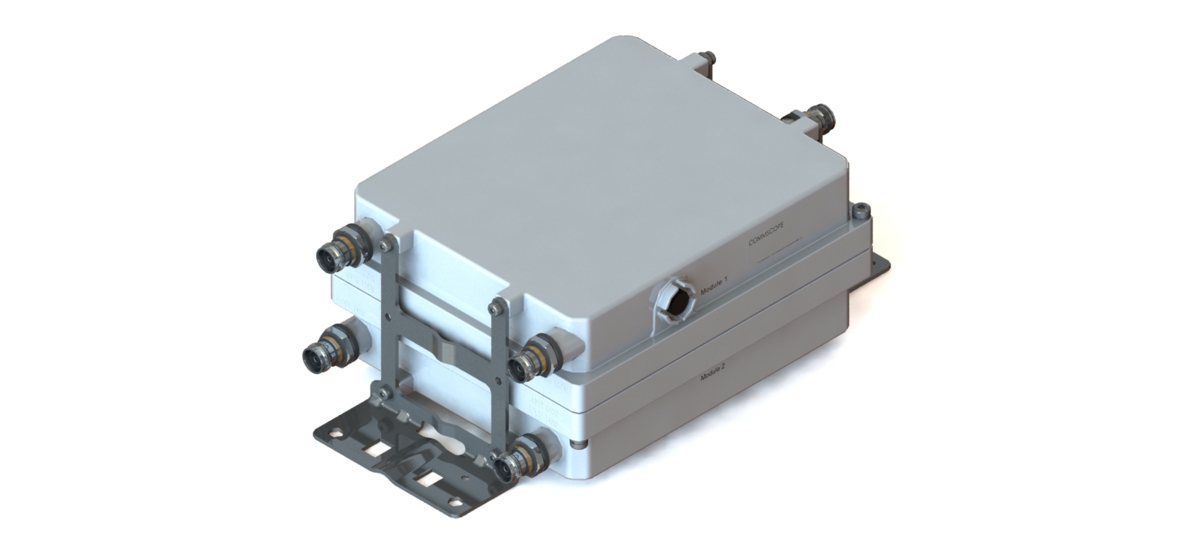
Dual Band Tower Mounted Amplifier, 800/900 MHz, 700MHz Bypass, 12 dB, 2 BTS & 4 ANT ports, AISG with 1 RET connector, with 4.3-10 connectors (2 device with 2 sub-units)
Features and Benefits
- Designed to boost UP-Link Coverage and KPIs
- 2 input ports and 4 output ports
- 2 devices with 2 sub-units
- Single AISG with 1 RET connector
- New 4.3-10 connectors for improved PIM performance and size reduction
Specifications
Product Classification
| Product Type | 2-BTS:4-ANT (Diplex) | Tower mounted amplifier |
General Specifications
| Color | Gray |
| Modularity | 2-Twin |
| Mounting Pipe Hardware | Band clamps (2) |
| RF Connector Interface | 4.3-10 Female |
Dimensions
| Height | 271 mm | 10.669 in |
| Width | 230 mm | 9.055 in |
| Depth | 128 mm | 5.039 in |
| Mounting Pipe Diameter Range | 42.6–122 mm |
Outline Drawing
| Click on image to enlarge. |

Electrical Specifications
| License Band, LNA | CEL 900 | EDD 800 |
Electrical Specifications, dc Power/Alarm
| dc Switching/Redundancy | Yes |
| Lightning Surge Current | 10 kA |
| Lightning Surge Current Waveform | 8/20 waveform |
| Voltage | 7–30 Vdc |
Electrical Specifications, AISG
| AISG Connector | 8-pin DIN Female |
| AISG Connector Standard | IEC 60130-9 |
| Protocol | AISG 2.0 |
| Voltage, AISG Mode | 10–30 Vdc |
Electrical Specifications
| Sub-module | 1 | 2 | 1 | 2 |
| Branch | 1 | 2 |
| Port Designation | ANT 800 | ANT 900 |
| License Band | EDD 800, LNA | CEL 900, LNA |
Electrical Specifications, Band Pass
| Frequency Range, MHz | 694–788 | |
| Insertion Loss, typical, dB | 0.20 | |
| Total Group Delay, typical, ns | 20 | |
| Return Loss, typical, dB | 20 | |
| Input Power, RMS, maximum, W | 200 | |
| Input Power, PEP, maximum, W | 1,000 | |
| 3rd Order PIM, typical, dBc | -160 | |
| 3rd Order PIM Test Method | Two +43 dBm carriers |
Electrical Specifications, Rx Uplink
| Frequency Range, MHz | 832–862 | 880–915 |
| Bandwidth, MHz | 30.00 | 35.00 |
| Gain, nominal, dB | 12.0 | 12.0 |
| Noise Figure, typical, dB | 1.3 | 1.3 |
| Total Group Delay, typical, ns | 200 | 200 |
| Return Loss, typical, dB | 20 | 20 |
| Insertion Loss - Bypass Mode, typical, dB | 2.8 | 2.9 |
| Return Loss - Bypass Mode, typical, dB | 16 | 16 |
Electrical Specifications, Tx Downlink
| Frequency Range, MHz | 791–821 | 925–960 |
| Bandwidth, MHz | 30.00 | 35.00 |
| Insertion Loss, typical, dB | 0.40 | 0.40 |
| Total Group Delay, typical, ns | 60 | 60 |
| Return Loss, typical, dB | 20 | 20 |
| Input Power, RMS, maximum, W | 200 | 200 |
| Input Power, PEP, maximum, W | 1,000 | 2,000 |
| 3rd Order PIM, typical, dBc | -160 | -160 |
| 3rd Order PIM Test Method | Two +43 dBm carriers | Two +43 dBm carriers |
Block Diagram
| Click on image to enlarge. |

Environmental Specifications
| Operating Temperature | -40 °C to +65 °C (-40 °F to +149 °F) |
| Corrosion Test Method | IEC 60068-2-11, 30 days |
| Environmental Test Method | ETSI EN 300 019-1-4 |
| Ingress Protection Test Method | IEC 60529:2001, IP67 |
Packaging and Weights
| Included | Mounting hardware |
| Volume | 7.95 L |
| Weight, net | 10.2 kg | 22.487 lb |
| Weight, without mounting hardware | 9.6 kg | 21.164 lb |
Product Classification
| Product Type | 2-BTS:4-ANT (Diplex) | Tower mounted amplifier |
General Specifications
| Color | Gray |
| Modularity | 2-Twin |
| Mounting Pipe Hardware | Band clamps (2) |
| RF Connector Interface | 4.3-10 Female |
Dimensions
| Height | 271 mm | 10.669 in |
| Width | 230 mm | 9.055 in |
| Depth | 128 mm | 5.039 in |
| Mounting Pipe Diameter Range | 42.6–122 mm |
Electrical Specifications
| License Band, LNA | CEL 900 | EDD 800 |
Electrical Specifications, dc Power/Alarm
| dc Switching/Redundancy | Yes |
| Lightning Surge Current | 10 kA |
| Lightning Surge Current Waveform | 8/20 waveform |
| Voltage | 7–30 Vdc |
Electrical Specifications, AISG
| AISG Connector | 8-pin DIN Female |
| AISG Connector Standard | IEC 60130-9 |
| Protocol | AISG 2.0 |
| Voltage, AISG Mode | 10–30 Vdc |
Electrical Specifications
| Sub-module | 1 | 2 | 1 | 2 |
| Branch | 1 | 2 |
| Port Designation | ANT 800 | ANT 900 |
| License Band | EDD 800, LNA | CEL 900, LNA |
Electrical Specifications, Band Pass
| Frequency Range, MHz | 694–788 | |
| Insertion Loss, typical, dB | 0.20 | |
| Total Group Delay, typical, ns | 20 | |
| Return Loss, typical, dB | 20 | |
| Input Power, RMS, maximum, W | 200 | |
| Input Power, PEP, maximum, W | 1,000 | |
| 3rd Order PIM, typical, dBc | -160 | |
| 3rd Order PIM Test Method | Two +43 dBm carriers |
Electrical Specifications, Rx Uplink
| Frequency Range, MHz | 832–862 | 880–915 |
| Bandwidth, MHz | 30.00 | 35.00 |
| Gain, nominal, dB | 12.0 | 12.0 |
| Noise Figure, typical, dB | 1.3 | 1.3 |
| Total Group Delay, typical, ns | 200 | 200 |
| Return Loss, typical, dB | 20 | 20 |
| Insertion Loss - Bypass Mode, typical, dB | 2.8 | 2.9 |
| Return Loss - Bypass Mode, typical, dB | 16 | 16 |
Electrical Specifications, Tx Downlink
| Frequency Range, MHz | 791–821 | 925–960 |
| Bandwidth, MHz | 30.00 | 35.00 |
| Insertion Loss, typical, dB | 0.40 | 0.40 |
| Total Group Delay, typical, ns | 60 | 60 |
| Return Loss, typical, dB | 20 | 20 |
| Input Power, RMS, maximum, W | 200 | 200 |
| Input Power, PEP, maximum, W | 1,000 | 2,000 |
| 3rd Order PIM, typical, dBc | -160 | -160 |
| 3rd Order PIM Test Method | Two +43 dBm carriers | Two +43 dBm carriers |
Environmental Specifications
| Operating Temperature | -40 °C to +65 °C (-40 °F to +149 °F) |
| Corrosion Test Method | IEC 60068-2-11, 30 days |
| Environmental Test Method | ETSI EN 300 019-1-4 |
| Ingress Protection Test Method | IEC 60529:2001, IP67 |
Packaging and Weights
| Included | Mounting hardware |
| Volume | 7.95 L |
| Weight, net | 10.2 kg | 22.487 lb |
| Weight, without mounting hardware | 9.6 kg | 21.164 lb |
| Click on image to enlarge. |
| Click on image to enlarge. |
Documentation & Downloads
Installation Instruction
Product Specification
Video
Filter Products – Designed for PIM Excellence

Filter Products – Designed for PIM Excellence
Warranty
Installation Instruction
Product Compliance Documentation
Product Specification
Video
Filter Products – Designed for PIM Excellence
Filter Products – Designed for PIM Excellence
Warranty
Other Ways to Browse
