E15R05P19
Tower Mounted Amplifier, Twin Upper C 700 MHz with AISG and Variable Gain
Specifications
Specifications
Product Classification
| Product Type | 1-BTS:1-ANT (Uniplex) | Tower mounted amplifier |
General Specifications
| Color | Gray |
| Modularity | 2-Twin |
| Mounting | Pole | Wall |
| Mounting Pipe Hardware | Band clamps (4) |
| RF Connector Interface | 7-16 DIN Female |
Dimensions
| Height | 290 mm | 11.417 in |
| Width | 252.5 mm | 9.941 in |
| Depth | 162 mm | 6.378 in |
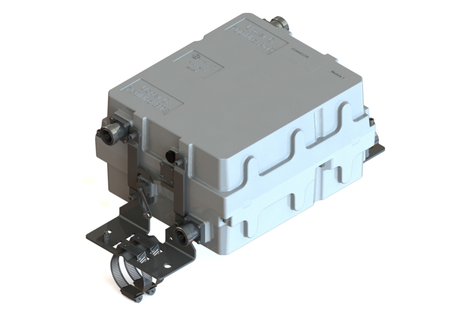
Outline Drawing
| Click on image to enlarge. |

Electrical Specifications
| License Band, LNA | USA 750 |
Electrical Specifications, dc Power/Alarm
| dc Switching/Redundancy | Yes |
| Lightning Surge Current | 10 kA |
| Lightning Surge Current Waveform | 8/20 waveform |
| Operating Current at Voltage | 140 mA @ 12 V |
| Operating Current Tolerance | ±15 mA |
| Voltage | 10–30 Vdc |
| Voltage, CWA Mode | 10–18 Vdc |
| Alarm Current, CWA Mode | 180–200 mA @ 10–18 V |
Electrical Specifications, AISG
| AISG Carrier | 2.176 MHz ± 100 ppm |
| AISG Connector | 8-pin DIN Female |
| AISG Connector Standard | IEC 60130-9 |
| Default Protocol | AISG 2.0 |
| Protocol | AISG 1.1 | AISG 2.0 |
| Voltage, AISG Mode | 10–30 Vdc |
Electrical Specifications
| Sub-module | 1 | 2 |
| Branch | 1 | 1 |
| Port Designation | ANT 0 | ANT 1 |
| AISG 2.0 Device Subunit | 1.a | 1.b |
| License Band | USA 750, LNA | USA 750, LNA |
Electrical Specifications, Band Reject
| Frequency Range, MHz | 763–775 | 763–775 |
| Attenuation, minimum, dB | 40.0 | 40.0 |
Electrical Specifications, Rx Uplink
| Frequency Range, MHz | 777.5–787 | 777.5–787 |
| Bandwidth, MHz | 9.50 | 9.50 |
| Gain, nominal, dB | 13.0 | 13.0 |
| Gain Tolerance, dB | ±1.0 | ±1.0 |
| Gain Adjustment Range, dB | 4–13 | 4–13 |
| Gain Adjustment Range Increments, dB | 1 | 1 |
| Noise Figure, typical, dB | 1.2 | 1.2 |
| Noise Figure at 8 dB, typical, dB | 1.5 | 1.5 |
| Noise Figure at 4 dB, typical, dB | 2.2 | 2.2 |
| Total Group Delay, maximum, ns | 330 | 330 |
| Return Loss, typical, dB | 24 | 24 |
| Return Loss at 8 dB, typical, dB | 22 | 22 |
| Return Loss at 4 dB, typical, dB | 20 | 20 |
| Insertion Loss - Bypass Mode, typical, dB | 2.3 | 2.3 |
| Return Loss - Bypass Mode, typical, dB | 16 | 16 |
| TX Band Rejection, minimum, dB | 80 | 80 |
Electrical Specifications, Tx Downlink
| Frequency Range, MHz | 746–756 | 746–756 |
| Bandwidth, MHz | 10.00 | 10.00 |
| Insertion Loss, maximum, dB | 0.40 | 0.40 |
| Insertion Loss, typical, dB | 0.35 | 0.35 |
| Total Group Delay, maximum, ns | 70 | 70 |
| Return Loss, minimum, dB | 24 | 24 |
| RX Band Rejection, minimum, dB | 40 | 40 |
| Input Power, RMS, maximum, W | 100 | 100 |
| Input Power, PEP, maximum, W | 1,000 | 1,000 |
| 5th Order PIM, maximum, dBc | -150 | -150 |
| 5th Order PIM Test Method | 2 x 20 W CW tones | 2 x 20 W CW tones |
Block Diagram
| Click on image to enlarge. |

Material Specifications
| Finish | Painted |
Mechanical Specifications
| Wind Speed, maximum | 241 km/h (150 mph) |
Environmental Specifications
| Operating Temperature | -40 °C to +65 °C (-40 °F to +149 °F) |
| Corrosion Test Method | IEC 60068-2-11, 30 days |
| Ingress Protection Test Method | IEC 60529:2001, IP67 |
Packaging and Weights
| Included | Mounting hardware |
| Weight, net | 12.5 kg | 27.558 lb |
Product Classification
| Product Type | 1-BTS:1-ANT (Uniplex) | Tower mounted amplifier |
General Specifications
| Color | Gray |
| Modularity | 2-Twin |
| Mounting | Pole | Wall |
| Mounting Pipe Hardware | Band clamps (4) |
| RF Connector Interface | 7-16 DIN Female |
Dimensions
| Height | 290 mm | 11.417 in |
| Width | 252.5 mm | 9.941 in |
| Depth | 162 mm | 6.378 in |
Electrical Specifications
| License Band, LNA | USA 750 |
Electrical Specifications, dc Power/Alarm
| dc Switching/Redundancy | Yes |
| Lightning Surge Current | 10 kA |
| Lightning Surge Current Waveform | 8/20 waveform |
| Operating Current at Voltage | 140 mA @ 12 V |
| Operating Current Tolerance | ±15 mA |
| Voltage | 10–30 Vdc |
| Voltage, CWA Mode | 10–18 Vdc |
| Alarm Current, CWA Mode | 180–200 mA @ 10–18 V |
Electrical Specifications, AISG
| AISG Carrier | 2.176 MHz ± 100 ppm |
| AISG Connector | 8-pin DIN Female |
| AISG Connector Standard | IEC 60130-9 |
| Default Protocol | AISG 2.0 |
| Protocol | AISG 1.1 | AISG 2.0 |
| Voltage, AISG Mode | 10–30 Vdc |
Electrical Specifications
| Sub-module | 1 | 2 |
| Branch | 1 | 1 |
| Port Designation | ANT 0 | ANT 1 |
| AISG 2.0 Device Subunit | 1.a | 1.b |
| License Band | USA 750, LNA | USA 750, LNA |
Electrical Specifications, Band Reject
| Frequency Range, MHz | 763–775 | 763–775 |
| Attenuation, minimum, dB | 40.0 | 40.0 |
Electrical Specifications, Rx Uplink
| Frequency Range, MHz | 777.5–787 | 777.5–787 |
| Bandwidth, MHz | 9.50 | 9.50 |
| Gain, nominal, dB | 13.0 | 13.0 |
| Gain Tolerance, dB | ±1.0 | ±1.0 |
| Gain Adjustment Range, dB | 4–13 | 4–13 |
| Gain Adjustment Range Increments, dB | 1 | 1 |
| Noise Figure, typical, dB | 1.2 | 1.2 |
| Noise Figure at 8 dB, typical, dB | 1.5 | 1.5 |
| Noise Figure at 4 dB, typical, dB | 2.2 | 2.2 |
| Total Group Delay, maximum, ns | 330 | 330 |
| Return Loss, typical, dB | 24 | 24 |
| Return Loss at 8 dB, typical, dB | 22 | 22 |
| Return Loss at 4 dB, typical, dB | 20 | 20 |
| Insertion Loss - Bypass Mode, typical, dB | 2.3 | 2.3 |
| Return Loss - Bypass Mode, typical, dB | 16 | 16 |
| TX Band Rejection, minimum, dB | 80 | 80 |
Electrical Specifications, Tx Downlink
| Frequency Range, MHz | 746–756 | 746–756 |
| Bandwidth, MHz | 10.00 | 10.00 |
| Insertion Loss, maximum, dB | 0.40 | 0.40 |
| Insertion Loss, typical, dB | 0.35 | 0.35 |
| Total Group Delay, maximum, ns | 70 | 70 |
| Return Loss, minimum, dB | 24 | 24 |
| RX Band Rejection, minimum, dB | 40 | 40 |
| Input Power, RMS, maximum, W | 100 | 100 |
| Input Power, PEP, maximum, W | 1,000 | 1,000 |
| 5th Order PIM, maximum, dBc | -150 | -150 |
| 5th Order PIM Test Method | 2 x 20 W CW tones | 2 x 20 W CW tones |
Material Specifications
| Finish | Painted |
Mechanical Specifications
| Wind Speed, maximum | 241 km/h (150 mph) |
Environmental Specifications
| Operating Temperature | -40 °C to +65 °C (-40 °F to +149 °F) |
| Corrosion Test Method | IEC 60068-2-11, 30 days |
| Ingress Protection Test Method | IEC 60529:2001, IP67 |
Packaging and Weights
| Included | Mounting hardware |
| Weight, net | 12.5 kg | 27.558 lb |
| Click on image to enlarge. |
| Click on image to enlarge. |
Documentation & Downloads
Installation Instruction
Product Specification
Video
Filter Products – Designed for PIM Excellence

Filter Products – Designed for PIM Excellence
Warranty
Installation Instruction
Product Compliance Documentation
Product Specification
Video
Filter Products – Designed for PIM Excellence
Filter Products – Designed for PIM Excellence
Warranty
Other Ways to Browse
