TMAT7UC21X-21AV | E15R02P50
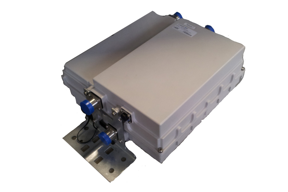
Twin Dual Band Upper 700C MHz/AWS1-4, Diplexer BTS, Variable Gain
Specifications
Specifications
Product Classification
| Product Type | 1-BTS:2-ANT (Diplex) | Tower mounted amplifier |
General Specifications
| Color | Gray |
| Modularity | 2-Twin |
| Mounting | Pole | Wall |
| Mounting Pipe Hardware | Band clamps (4) |
| RF Connector Interface | 7-16 DIN Female |
| RF Connector Interface Body Style | Long neck |
Dimensions
| Height | 320 mm | 12.598 in |
| Width | 310 mm | 12.205 in |
| Depth | 154 mm | 6.063 in |
| Ground Screw Diameter | 6 mm | 0.236 in |
| Mounting Pipe Diameter Range | 40–160 mm |
Outline Drawing
| Click on image to enlarge. |

Electrical Specifications
| License Band, LNA | AWS 1700 | USA 750 |
Electrical Specifications, dc Power/Alarm
| dc Switching/Redundancy | Yes |
| Lightning Surge Current | 10 kA |
| Lightning Surge Current Waveform | 8/20 waveform |
| Operating Current at Voltage | 240 mA @ 12 V |
| Operating Current Tolerance | ±20 mA |
| Voltage | 7–30 Vdc |
| Voltage, CWA Mode | 10–18 Vdc |
| Alarm Current, CWA Mode | 30–170 mA @ 10–18 V |
Electrical Specifications, AISG
| AISG Carrier | 2.176 MHz ± 100 ppm |
| AISG Connector | 8-pin DIN Female |
| AISG Connector Standard | IEC 60130-9 |
| Default Protocol | AISG 2.0 |
| Protocol | AISG 1.1 | AISG 2.0 |
| Voltage, AISG Mode | 10–30 Vdc |
Electrical Specifications
| Sub-module | 1 | 2 | 1 | 2 |
| Branch | 1 | 2 |
| Port Designation | ANT | ANT |
| AISG 2.0 Device Subunit | E15R02P50 1/2 | E15R02P50 2/4 |
| License Band | USA 750, LNA | AWS 1700, LNA |
Electrical Specifications, Band Reject
| Frequency Range, MHz | 763–775 | |
| Attenuation, minimum, dB | 40.0 |
Electrical Specifications, Rx Uplink
| Frequency Range, MHz | 777.5–787 | 1695–1780 |
| Gain, nominal, dB | 13.0 | 12.0 |
| Gain Tolerance, dB | ±1.0 | +1.3/-1.0 |
| Gain Adjustment Range, dB | 4-13 | 4-12 |
| Gain Adjustment Range Increments, dB | 1 | 1 |
| Noise Figure, typical, dB | 1.8 | 1.6 |
| Noise Figure at 8 dB, typical, dB | 2.1 | 2.0 |
| Noise Figure at 4 dB, typical, dB | 3.1 | 2.6 |
| Total Group Delay, maximum, ns | 330 | 70 |
| Return Loss, typical, dB | 24 | 24 |
| Return Loss at 8 dB, typical, dB | 22 | 22 |
| Return Loss at 4 dB, typical, dB | 20 | 20 |
| Insertion Loss - Bypass Mode, typical, dB | 3.0 | 2.3 |
| Return Loss - Bypass Mode, typical, dB | 14 | 14 |
Electrical Specifications, Tx Downlink
| Frequency Range, MHz | 746–756 | 2110–2200 |
| Insertion Loss, maximum, dB | 0.40 | 0.40 |
| Total Group Delay, maximum, ns | 70 | 30 |
| Return Loss, minimum, dB | 24 | 24 |
| Input Power, RMS, maximum, W | 400 | 300 |
| Input Power, PEP, maximum, W | 4,000 | 5,000 |
| 7th Order PIM, minimum, dBc | -161 | |
| 7th Order PIM Test Method | 2 x 20 W CW tones | |
| Higher Order PIM, minimum, dBc | -161.000000 | |
| Higher Order PIM Test Method | 2 x 20 W CW tones |
Block Diagram
| Click on image to enlarge. |

Material Specifications
| Finish | Painted |
Environmental Specifications
| Operating Temperature | -40 °C to +65 °C (-40 °F to +149 °F) |
| Relative Humidity | Up to 100% |
| Corrosion Test Method | IEC 60068-2-11, 30 days |
| Ingress Protection Test Method | IEC 60529:2001, IP67 |
Packaging and Weights
| Included | Mounting hardware |
| Weight, net | 14.5 kg | 31.967 lb |
Product Classification
| Product Type | 1-BTS:2-ANT (Diplex) | Tower mounted amplifier |
General Specifications
| Color | Gray |
| Modularity | 2-Twin |
| Mounting | Pole | Wall |
| Mounting Pipe Hardware | Band clamps (4) |
| RF Connector Interface | 7-16 DIN Female |
| RF Connector Interface Body Style | Long neck |
Dimensions
| Height | 320 mm | 12.598 in |
| Width | 310 mm | 12.205 in |
| Depth | 154 mm | 6.063 in |
| Ground Screw Diameter | 6 mm | 0.236 in |
| Mounting Pipe Diameter Range | 40–160 mm |
Electrical Specifications
| License Band, LNA | AWS 1700 | USA 750 |
Electrical Specifications, dc Power/Alarm
| dc Switching/Redundancy | Yes |
| Lightning Surge Current | 10 kA |
| Lightning Surge Current Waveform | 8/20 waveform |
| Operating Current at Voltage | 240 mA @ 12 V |
| Operating Current Tolerance | ±20 mA |
| Voltage | 7–30 Vdc |
| Voltage, CWA Mode | 10–18 Vdc |
| Alarm Current, CWA Mode | 30–170 mA @ 10–18 V |
Electrical Specifications, AISG
| AISG Carrier | 2.176 MHz ± 100 ppm |
| AISG Connector | 8-pin DIN Female |
| AISG Connector Standard | IEC 60130-9 |
| Default Protocol | AISG 2.0 |
| Protocol | AISG 1.1 | AISG 2.0 |
| Voltage, AISG Mode | 10–30 Vdc |
Electrical Specifications
| Sub-module | 1 | 2 | 1 | 2 |
| Branch | 1 | 2 |
| Port Designation | ANT | ANT |
| AISG 2.0 Device Subunit | E15R02P50 1/2 | E15R02P50 2/4 |
| License Band | USA 750, LNA | AWS 1700, LNA |
Electrical Specifications, Band Reject
| Frequency Range, MHz | 763–775 | |
| Attenuation, minimum, dB | 40.0 |
Electrical Specifications, Rx Uplink
| Frequency Range, MHz | 777.5–787 | 1695–1780 |
| Gain, nominal, dB | 13.0 | 12.0 |
| Gain Tolerance, dB | ±1.0 | +1.3/-1.0 |
| Gain Adjustment Range, dB | 4-13 | 4-12 |
| Gain Adjustment Range Increments, dB | 1 | 1 |
| Noise Figure, typical, dB | 1.8 | 1.6 |
| Noise Figure at 8 dB, typical, dB | 2.1 | 2.0 |
| Noise Figure at 4 dB, typical, dB | 3.1 | 2.6 |
| Total Group Delay, maximum, ns | 330 | 70 |
| Return Loss, typical, dB | 24 | 24 |
| Return Loss at 8 dB, typical, dB | 22 | 22 |
| Return Loss at 4 dB, typical, dB | 20 | 20 |
| Insertion Loss - Bypass Mode, typical, dB | 3.0 | 2.3 |
| Return Loss - Bypass Mode, typical, dB | 14 | 14 |
Electrical Specifications, Tx Downlink
| Frequency Range, MHz | 746–756 | 2110–2200 |
| Insertion Loss, maximum, dB | 0.40 | 0.40 |
| Total Group Delay, maximum, ns | 70 | 30 |
| Return Loss, minimum, dB | 24 | 24 |
| Input Power, RMS, maximum, W | 400 | 300 |
| Input Power, PEP, maximum, W | 4,000 | 5,000 |
| 7th Order PIM, minimum, dBc | -161 | |
| 7th Order PIM Test Method | 2 x 20 W CW tones | |
| Higher Order PIM, minimum, dBc | -161.000000 | |
| Higher Order PIM Test Method | 2 x 20 W CW tones |
Material Specifications
| Finish | Painted |
Environmental Specifications
| Operating Temperature | -40 °C to +65 °C (-40 °F to +149 °F) |
| Relative Humidity | Up to 100% |
| Corrosion Test Method | IEC 60068-2-11, 30 days |
| Ingress Protection Test Method | IEC 60529:2001, IP67 |
Packaging and Weights
| Included | Mounting hardware |
| Weight, net | 14.5 kg | 31.967 lb |
| Click on image to enlarge. |
| Click on image to enlarge. |
Documentation & Downloads
Installation Instruction
Product Specification
Video
Filter Products – Designed for PIM Excellence

Filter Products – Designed for PIM Excellence
Warranty
Installation Instruction
Product Compliance Documentation
Product Specification
Video
Filter Products – Designed for PIM Excellence
Filter Products – Designed for PIM Excellence
Warranty
Other Ways to Browse
