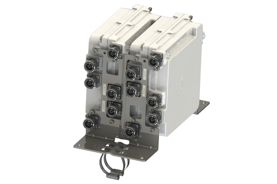
TMA2T1921XB68-31AV | E15Z01P41
2pack Twin Diplexed BTS Port, Dual Band PCS/AWS 1-3 555–894 MHz Bypass with AISG and Variable Gain
Specifications
Specifications
Product Classification
| Product Type | 1-BTS:3-ANT (Triplex) | Tower mounted amplifier |
General Specifications
| Color | Gray |
| Modularity | 4-Quad |
| Mounting | Pole | Wall |
| Mounting Pipe Hardware | Band clamps (2) |
| RF Connector Interface | 7-16 DIN Female |
| RF Connector Interface Body Style | Long neck |
Dimensions
| Height | 245 mm | 9.646 in |
| Width | 250 mm | 9.843 in |
| Depth | 215 mm | 8.465 in |
| Mounting Pipe Diameter Range | 42.6–122 mm |
Outline Drawing
| Click on image to enlarge. |

Electrical Specifications
| License Band, Band Pass | APT 700 | CEL 850 | LMR 750 | LMR 800 | USA 700 | USA 750 |
| License Band, LNA | AWS 1700 | PCS 1900 |
Electrical Specifications, dc Power/Alarm
| Lightning Surge Current | 10 kA |
| Lightning Surge Current Waveform | 8/20 waveform |
| Operating Current at Voltage | 240 mA @ 12 V |
| Operating Current Tolerance | ±20 mA |
| Voltage | 7–30 Vdc |
| Voltage, CWA Mode | 10–18 Vdc |
| Alarm Current, CWA Mode | 30–170 mA |
Electrical Specifications, AISG
| AISG Connector | 8-pin DIN Female |
| AISG Connector Standard | IEC 60130-9 |
| Default Protocol | AISG 2.0 |
| Protocol | AISG 1.1 | AISG 2.0 |
| Voltage, AISG Mode | 10–30 Vdc |
Electrical Specifications
| Sub-module | 1 | 2 | 3 | 4 | 1 | 2 | 3 | 4 | 1 | 2 | 3 | 4 |
| Branch | 1 | 2 | 3 |
| Port Designation | ANT 555-894 | ANT AWS | ANT PCS |
| AISG 2.0 Device Subunit | E25A01P03 1 | E25A01P03 2 | E25A01P03 3 |
| License Band | APT 700, Band Pass CEL 850, Band Pass LMR 750, Band Pass LMR 800, Band Pass USA 700, Band Pass USA 750, Band Pass | AWS 1700, LNA | PCS 1900, LNA |
Electrical Specifications, Band Pass
| Frequency Range, MHz | 555–894 | ||
| Insertion Loss, maximum, dB | 0.20 | ||
| Insertion Loss, typical, dB | 0.10 | ||
| Total Group Delay, maximum, ns | 8 | ||
| Return Loss, minimum, dB | 20 | ||
| Input Power, RMS, maximum, W | 200 | ||
| Input Power, PEP, maximum, W | 3,000 | ||
| 3rd Order PIM, typical, dBc | -153 | ||
| 3rd Order PIM Test Method | 2 x 20 W CW tones |
Electrical Specifications, Rx Uplink
| Frequency Range, MHz | 1695–1780 | 1850–1910 | |
| Bandwidth, MHz | 85.00 | 60.00 | |
| Gain, nominal, dB | 12.0 | 12.0 | |
| Gain Tolerance, dB | +1.3/-1.0 | ±1 | |
| Gain Adjustment Range, dB | 12-4 | 12-4 | |
| Gain Adjustment Range Increments, dB | 1 | 1 | |
| Noise Figure, typical, dB | 1.3 | 1.3 | |
| Noise Figure at 8 dB, typical, dB | 1.6 | 1.7 | |
| Noise Figure at 4 dB, typical, dB | 2.1 | 2.1 | |
| Total Group Delay, maximum, ns | 80 | 150 | |
| Return Loss, typical, dB | 20 | 20 | |
| Return Loss at 8 dB, typical, dB | 20 | 20 | |
| Return Loss at 4 dB, typical, dB | 20 | 20 | |
| Insertion Loss - Bypass Mode, typical, dB | 1.7 | 2.2 | |
| Return Loss - Bypass Mode, typical, dB | 16 | 16 | |
| TX Band Rejection, minimum, dB | 60 |
Electrical Specifications, Tx Downlink
| Frequency Range, MHz | 2110–2200 | 1930–1990 | |
| Bandwidth, MHz | 90.00 | 60.00 | |
| Insertion Loss, maximum, dB | 0.35 | 0.60 | |
| Insertion Loss, typical, dB | 0.20 | 0.45 | |
| Total Group Delay, maximum, ns | 50 | 50 | |
| Return Loss, minimum, dB | 20 | 20 | |
| Input Power, RMS, maximum, W | 200 | 200 | |
| Input Power, PEP, maximum, W | 3,000 | 3,000 | |
| 3rd Order PIM, typical, dBc | -153 | ||
| 3rd Order PIM Test Method | 2 x 20 W CW tones | ||
| Higher Order PIM, typical, dBc | -153 | ||
| Higher Order PIM Test Method | 1 x 20 W AWS CW tone 1 x 20 W PCS CW tone |
Block Diagram
| Click on image to enlarge. |

Material Specifications
| Finish | Painted |
Environmental Specifications
| Operating Temperature | -40 °C to +65 °C (-40 °F to +149 °F) |
| Relative Humidity | Up to 100% |
| Corrosion Test Method | IEC 60068-2-11, 30 days |
| Ingress Protection Test Method | IEC 60529:2001, IP67 |
Packaging and Weights
| Included | Mounting hardware |
| Weight, net | 19.2 kg | 42.329 lb |
Product Classification
| Product Type | 1-BTS:3-ANT (Triplex) | Tower mounted amplifier |
General Specifications
| Color | Gray |
| Modularity | 4-Quad |
| Mounting | Pole | Wall |
| Mounting Pipe Hardware | Band clamps (2) |
| RF Connector Interface | 7-16 DIN Female |
| RF Connector Interface Body Style | Long neck |
Dimensions
| Height | 245 mm | 9.646 in |
| Width | 250 mm | 9.843 in |
| Depth | 215 mm | 8.465 in |
| Mounting Pipe Diameter Range | 42.6–122 mm |
Electrical Specifications
| License Band, Band Pass | APT 700 | CEL 850 | LMR 750 | LMR 800 | USA 700 | USA 750 |
| License Band, LNA | AWS 1700 | PCS 1900 |
Electrical Specifications, dc Power/Alarm
| Lightning Surge Current | 10 kA |
| Lightning Surge Current Waveform | 8/20 waveform |
| Operating Current at Voltage | 240 mA @ 12 V |
| Operating Current Tolerance | ±20 mA |
| Voltage | 7–30 Vdc |
| Voltage, CWA Mode | 10–18 Vdc |
| Alarm Current, CWA Mode | 30–170 mA |
Electrical Specifications, AISG
| AISG Connector | 8-pin DIN Female |
| AISG Connector Standard | IEC 60130-9 |
| Default Protocol | AISG 2.0 |
| Protocol | AISG 1.1 | AISG 2.0 |
| Voltage, AISG Mode | 10–30 Vdc |
Electrical Specifications
| Sub-module | 1 | 2 | 3 | 4 | 1 | 2 | 3 | 4 | 1 | 2 | 3 | 4 |
| Branch | 1 | 2 | 3 |
| Port Designation | ANT 555-894 | ANT AWS | ANT PCS |
| AISG 2.0 Device Subunit | E25A01P03 1 | E25A01P03 2 | E25A01P03 3 |
| License Band | APT 700, Band Pass; CEL 850, Band Pass; LMR 750, Band Pass; LMR 800, Band Pass; USA 700, Band Pass; USA 750, Band Pass | AWS 1700, LNA | PCS 1900, LNA |
Electrical Specifications, Band Pass
| Frequency Range, MHz | 555–894 | ||
| Insertion Loss, maximum, dB | 0.20 | ||
| Insertion Loss, typical, dB | 0.10 | ||
| Total Group Delay, maximum, ns | 8 | ||
| Return Loss, minimum, dB | 20 | ||
| Input Power, RMS, maximum, W | 200 | ||
| Input Power, PEP, maximum, W | 3,000 | ||
| 3rd Order PIM, typical, dBc | -153 | ||
| 3rd Order PIM Test Method | 2 x 20 W CW tones |
Electrical Specifications, Rx Uplink
| Frequency Range, MHz | 1695–1780 | 1850–1910 | |
| Bandwidth, MHz | 85.00 | 60.00 | |
| Gain, nominal, dB | 12.0 | 12.0 | |
| Gain Tolerance, dB | +1.3/-1.0 | ±1 | |
| Gain Adjustment Range, dB | 12-4 | 12-4 | |
| Gain Adjustment Range Increments, dB | 1 | 1 | |
| Noise Figure, typical, dB | 1.3 | 1.3 | |
| Noise Figure at 8 dB, typical, dB | 1.6 | 1.7 | |
| Noise Figure at 4 dB, typical, dB | 2.1 | 2.1 | |
| Total Group Delay, maximum, ns | 80 | 150 | |
| Return Loss, typical, dB | 20 | 20 | |
| Return Loss at 8 dB, typical, dB | 20 | 20 | |
| Return Loss at 4 dB, typical, dB | 20 | 20 | |
| Insertion Loss - Bypass Mode, typical, dB | 1.7 | 2.2 | |
| Return Loss - Bypass Mode, typical, dB | 16 | 16 | |
| TX Band Rejection, minimum, dB | 60 |
Electrical Specifications, Tx Downlink
| Frequency Range, MHz | 2110–2200 | 1930–1990 | |
| Bandwidth, MHz | 90.00 | 60.00 | |
| Insertion Loss, maximum, dB | 0.35 | 0.60 | |
| Insertion Loss, typical, dB | 0.20 | 0.45 | |
| Total Group Delay, maximum, ns | 50 | 50 | |
| Return Loss, minimum, dB | 20 | 20 | |
| Input Power, RMS, maximum, W | 200 | 200 | |
| Input Power, PEP, maximum, W | 3,000 | 3,000 | |
| 3rd Order PIM, typical, dBc | -153 | ||
| 3rd Order PIM Test Method | 2 x 20 W CW tones | ||
| Higher Order PIM, typical, dBc | -153 | ||
| Higher Order PIM Test Method | 1 x 20 W AWS CW tone; 1 x 20 W PCS CW tone |
Material Specifications
| Finish | Painted |
Environmental Specifications
| Operating Temperature | -40 °C to +65 °C (-40 °F to +149 °F) |
| Relative Humidity | Up to 100% |
| Corrosion Test Method | IEC 60068-2-11, 30 days |
| Ingress Protection Test Method | IEC 60529:2001, IP67 |
Packaging and Weights
| Included | Mounting hardware |
| Weight, net | 19.2 kg | 42.329 lb |
| Click on image to enlarge. |
| Click on image to enlarge. |
Documentation & Downloads
Installation Instruction
Product Specification
Video
Filter Products – Designed for PIM Excellence

Filter Products – Designed for PIM Excellence
Warranty
Installation Instruction
Product Compliance Documentation
Product Specification
Video
Filter Products – Designed for PIM Excellence
Filter Products – Designed for PIM Excellence
Warranty
Other Ways to Browse
