E15S09P40
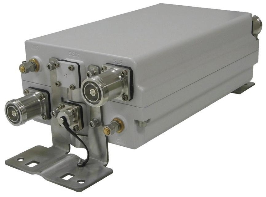
Tower Mounted Amplifier, Twin PCS A-G with Variable Gain AISG
Specifications
Product Classification
| Product Type | 1-BTS:1-ANT (Uniplex) | Tower mounted amplifier |
General Specifications
| Color | Gray |
| Modularity | 2-Twin |
| Mounting | Pole | Wall |
| Mounting Pipe Hardware | Band clamps (2) |
| RF Connector Interface | 7-16 DIN Female |
| RF Connector Interface Body Style | Long neck |
Dimensions
| Height | 260 mm | 10.236 in |
| Width | 170 mm | 6.693 in |
| Depth | 94 mm | 3.701 in |
| Ground Screw Diameter | 6 mm | 0.236 in |
| Mounting Pipe Diameter Range | 42.6–122 mm |
Outline Drawing
| Click on image to enlarge. |

Electrical Specifications
| License Band, LNA | PCS 1900 |
Electrical Specifications, dc Power/Alarm
| dc Switching/Redundancy | Yes |
| Lightning Surge Current | 10 kA |
| Lightning Surge Current Waveform | 8/20 waveform |
| Operating Current at Voltage | 135 mA @ 12 V |
| Operating Current Tolerance | ±10 mA |
| Voltage | 7–30 Vdc |
| Voltage, CWA Mode | 10–18 Vdc |
| Alarm Current, CWA Mode | 185 mA ±10 mA |
Electrical Specifications, AISG
| AISG Connector | 8-pin DIN Female |
| AISG Connector Standard | IEC 60130-9 |
| Default Protocol | AISG 2.0 |
| Protocol | AISG 1.1 | AISG 2.0 |
| Voltage, AISG Mode | 10–30 Vdc |
Electrical Specifications
| Sub-module | 1 | 2 |
| Branch | 1 |
| Port Designation | ANT |
| License Band | PCS 1900, LNA |
Electrical Specifications, Rx Uplink
| Frequency Range, MHz | 1850–1915 |
| Bandwidth, MHz | 65.00 |
| Gain, nominal, dB | 12.0 |
| Gain Tolerance, dB | ±1 |
| Gain Adjustment Range, dB | 12-4 |
| Gain Adjustment Range Increments, dB | 1 |
| Noise Figure, maximum, dB | 2.0 |
| Noise Figure at 8 dB, maximum, dB | 2.4 |
| Noise Figure at 4 dB, maximum, dB | 3.0 |
| Noise Figure, typical, dB | 1.3 |
| Noise Figure at 8 dB, typical, dB | 1.6 |
| Noise Figure at 4 dB, typical, dB | 2.3 |
| Group Delay Variation, maximum, ns | 50 |
| Group Delay Variation Bandwidth, MHz | 5.00 |
| Total Group Delay, maximum, ns | 150 |
| Output IP3, minimum, dBm | 26 |
| Output IP3 at 8 dB, minimum, dBm | 22 |
| Output IP3 at 4 dB, minimum, dBm | 18 |
| Return Loss, minimum, dB | 18 |
Electrical Specifications, Tx Downlink
| Frequency Range, MHz | 1930–1995 |
| Bandwidth, MHz | 65.00 |
| Insertion Loss, maximum, dB | 0.70 |
| Group Delay Variation, maximum, ns | 20 |
| Group Delay Variation Bandwidth, MHz | 5.00 |
| Total Group Delay, maximum, ns | 50 |
| Return Loss, minimum, dB | 18 |
| Input Power, RMS, maximum, W | 500 |
| Input Power, PEP, maximum, W | 5,000 |
| 3rd Order PIM, maximum, dBc | -153 |
| 3rd Order PIM Test Method | Two +43 dBm carriers |
| VSWR Alarm Threshold, dB | 9.54 |
| VSWR Alarm Threshold Tolerance, dB | ±2 |
Block Diagram
| Click on image to enlarge. |

Material Specifications
| Finish | Painted |
Environmental Specifications
| Operating Temperature | -40 °C to +65 °C (-40 °F to +149 °F) |
| Relative Humidity | Up to 100% |
| Corrosion Test Method | IEC 60068-2-11, 30 days |
| Ingress Protection Test Method | IEC 60529:2001, IP67 |
Packaging and Weights
| Included | Mounting hardware |
| Volume | 4.1 L |
| Weight, net | 6.6 kg | 14.55 lb |
Regulatory Compliance/Certifications
| Agency | Classification |
| ISO 9001:2015 | Designed, manufactured and/or distributed under this quality management system |
Product Classification
| Product Type | 1-BTS:1-ANT (Uniplex) | Tower mounted amplifier |
General Specifications
| Color | Gray |
| Modularity | 2-Twin |
| Mounting | Pole | Wall |
| Mounting Pipe Hardware | Band clamps (2) |
| RF Connector Interface | 7-16 DIN Female |
| RF Connector Interface Body Style | Long neck |
Dimensions
| Height | 260 mm | 10.236 in |
| Width | 170 mm | 6.693 in |
| Depth | 94 mm | 3.701 in |
| Ground Screw Diameter | 6 mm | 0.236 in |
| Mounting Pipe Diameter Range | 42.6–122 mm |
Electrical Specifications
| License Band, LNA | PCS 1900 |
Electrical Specifications, dc Power/Alarm
| dc Switching/Redundancy | Yes |
| Lightning Surge Current | 10 kA |
| Lightning Surge Current Waveform | 8/20 waveform |
| Operating Current at Voltage | 135 mA @ 12 V |
| Operating Current Tolerance | ±10 mA |
| Voltage | 7–30 Vdc |
| Voltage, CWA Mode | 10–18 Vdc |
| Alarm Current, CWA Mode | 185 mA ±10 mA |
Electrical Specifications, AISG
| AISG Connector | 8-pin DIN Female |
| AISG Connector Standard | IEC 60130-9 |
| Default Protocol | AISG 2.0 |
| Protocol | AISG 1.1 | AISG 2.0 |
| Voltage, AISG Mode | 10–30 Vdc |
Electrical Specifications
| Sub-module | 1 | 2 |
| Branch | 1 |
| Port Designation | ANT |
| License Band | PCS 1900, LNA |
Electrical Specifications, Rx Uplink
| Frequency Range, MHz | 1850–1915 |
| Bandwidth, MHz | 65.00 |
| Gain, nominal, dB | 12.0 |
| Gain Tolerance, dB | ±1 |
| Gain Adjustment Range, dB | 12-4 |
| Gain Adjustment Range Increments, dB | 1 |
| Noise Figure, maximum, dB | 2.0 |
| Noise Figure at 8 dB, maximum, dB | 2.4 |
| Noise Figure at 4 dB, maximum, dB | 3.0 |
| Noise Figure, typical, dB | 1.3 |
| Noise Figure at 8 dB, typical, dB | 1.6 |
| Noise Figure at 4 dB, typical, dB | 2.3 |
| Group Delay Variation, maximum, ns | 50 |
| Group Delay Variation Bandwidth, MHz | 5.00 |
| Total Group Delay, maximum, ns | 150 |
| Output IP3, minimum, dBm | 26 |
| Output IP3 at 8 dB, minimum, dBm | 22 |
| Output IP3 at 4 dB, minimum, dBm | 18 |
| Return Loss, minimum, dB | 18 |
Electrical Specifications, Tx Downlink
| Frequency Range, MHz | 1930–1995 |
| Bandwidth, MHz | 65.00 |
| Insertion Loss, maximum, dB | 0.70 |
| Group Delay Variation, maximum, ns | 20 |
| Group Delay Variation Bandwidth, MHz | 5.00 |
| Total Group Delay, maximum, ns | 50 |
| Return Loss, minimum, dB | 18 |
| Input Power, RMS, maximum, W | 500 |
| Input Power, PEP, maximum, W | 5,000 |
| 3rd Order PIM, maximum, dBc | -153 |
| 3rd Order PIM Test Method | Two +43 dBm carriers |
| VSWR Alarm Threshold, dB | 9.54 |
| VSWR Alarm Threshold Tolerance, dB | ±2 |
Material Specifications
| Finish | Painted |
Environmental Specifications
| Operating Temperature | -40 °C to +65 °C (-40 °F to +149 °F) |
| Relative Humidity | Up to 100% |
| Corrosion Test Method | IEC 60068-2-11, 30 days |
| Ingress Protection Test Method | IEC 60529:2001, IP67 |
Packaging and Weights
| Included | Mounting hardware |
| Volume | 4.1 L |
| Weight, net | 6.6 kg | 14.55 lb |
| Click on image to enlarge. |
| Click on image to enlarge. |
Regulatory Compliance/Certifications
| Agency | Classification |
| ISO 9001:2015 | Designed, manufactured and/or distributed under this quality management system |
Documentation & Downloads
Installation Instruction
Product Specification
Video
Filter Products – Designed for PIM Excellence

Filter Products – Designed for PIM Excellence
Warranty
Installation Instruction
Product Compliance Documentation
Product Specification
Video
Filter Products – Designed for PIM Excellence
Filter Products – Designed for PIM Excellence
Warranty
Other Ways to Browse
