E15R02P30
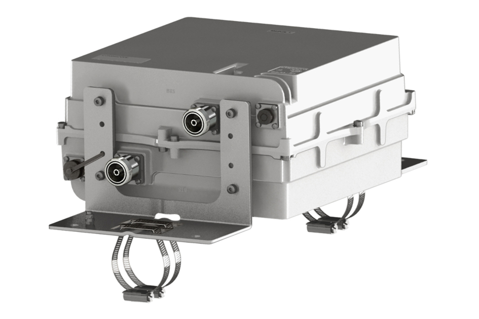
Dual Band Tower Mounted Amplifier, 850//900 MHz, 12 dB, 2 BTS & 2 ANT ports, AISG with 1 RET connector (2 device with 2 sub-units)
Specifications
Features and Benefits
- TMA is operating in AISG & CWA mode, Alarm Current consumption CWA mode 190 mA
- 2 input ports and 2 output ports
- Designed to boost UP-Link Coverage and KPIs
- Automatic LNA by-pass function
- Connectors “in line”
- Single AISG with 1 RET connector
- 2 devices with 2 sub-units
- Built in lightning protection
Specifications
Product Classification
| Product Type | 1-BTS:1-ANT (Uniplex) | Tower mounted amplifier |
General Specifications
| Color | Gray |
| Modularity | 2-Twin |
| Mounting Pipe Hardware | Band clamps (2) |
| RF Connector Interface | 7-16 DIN Female |
Dimensions
| Height | 152 mm | 5.984 in |
| Width | 284 mm | 11.181 in |
| Depth | 284 mm | 11.181 in |
| Mounting Pipe Diameter Range | 42.6–122 mm |
Outline Drawing
| Click on image to enlarge. |

Electrical Specifications
| License Band, LNA | CEL 850 | CEL 900 | EDD 800 |
Electrical Specifications, dc Power/Alarm
| dc Switching/Redundancy | Yes |
| Lightning Surge Current | 10 kA |
| Lightning Surge Current Waveform | 8/20 waveform |
| Alarm Current, CWA Mode | 190 mA ±10 mA |
Electrical Specifications, AISG
| AISG Connector | 8-pin DIN Female |
| AISG Connector Standard | IEC 60130-9 |
| Protocol | AISG 2.0 |
| Voltage, AISG Mode | 10–30 Vdc |
Electrical Specifications
| Sub-module | 1 | 2 | 1 | 2 |
| Branch | 1 | 2 |
| Port Designation | ANT | ANT |
| License Band | CEL 850, LNA | CEL 900, LNA |
Electrical Specifications, Rx Uplink
| Frequency Range, MHz | 825–835 | 898–915 |
| Bandwidth, MHz | 10.00 | 16.60 |
| Gain, nominal, dB | 13.0 | 13.0 |
| Noise Figure, maximum, dB | 2.0 | 2.0 |
| Noise Figure, typical, dB | 1.5 | 1.5 |
| Group Delay Variation, maximum, ns | 190 | 60 |
| Group Delay Variation Bandwidth, MHz | 5.00 | 5.00 |
| Return Loss, minimum, dB | 16 | 16 |
| Return Loss, typical, dB | 20 | 20 |
| Insertion Loss - Bypass Mode, typical, dB | 2.1 | 1.8 |
| Return Loss - Bypass Mode, typical, dB | 18 | 18 |
Electrical Specifications, Tx Downlink
| Frequency Range, MHz | 870–880 | 943–960 |
| Bandwidth, MHz | 10.00 | 16.60 |
| Insertion Loss, maximum, dB | 0.60 | 0.60 |
| Insertion Loss, typical, dB | 0.50 | 0.50 |
| Group Delay Variation, maximum, ns | 35 | 35 |
| Group Delay Variation Bandwidth, MHz | 5.00 | 5.00 |
| Return Loss, minimum, dB | 16 | 16 |
| Return Loss, typical, dB | 20 | 20 |
| Input Power, RMS, maximum, W | 200 | 200 |
| Input Power, PEP, maximum, W | 2,500 | 2,500 |
| 3rd Order PIM, typical, dBc | -153 | -153 |
| 3rd Order PIM Test Method | Two +43 dBm carriers | Two +43 dBm carriers |
Block Diagram
| Click on image to enlarge. |

Environmental Specifications
| Operating Temperature | -40 °C to +65 °C (-40 °F to +149 °F) |
| Relative Humidity | Up to 100% |
| Corrosion Test Method | IEC 60068-2-11, 30 days |
| Ingress Protection Test Method | IEC 60529:2001, IP67 |
Packaging and Weights
| Included | Mounting hardware |
| Volume | 12 L |
| Weight, net | 15 kg | 33.069 lb |
Regulatory Compliance/Certifications
| Agency | Classification |
| ISO 9001:2015 | Designed, manufactured and/or distributed under this quality management system |
Product Classification
| Product Type | 1-BTS:1-ANT (Uniplex) | Tower mounted amplifier |
General Specifications
| Color | Gray |
| Modularity | 2-Twin |
| Mounting Pipe Hardware | Band clamps (2) |
| RF Connector Interface | 7-16 DIN Female |
Dimensions
| Height | 152 mm | 5.984 in |
| Width | 284 mm | 11.181 in |
| Depth | 284 mm | 11.181 in |
| Mounting Pipe Diameter Range | 42.6–122 mm |
Electrical Specifications
| License Band, LNA | CEL 850 | CEL 900 | EDD 800 |
Electrical Specifications, dc Power/Alarm
| dc Switching/Redundancy | Yes |
| Lightning Surge Current | 10 kA |
| Lightning Surge Current Waveform | 8/20 waveform |
| Alarm Current, CWA Mode | 190 mA ±10 mA |
Electrical Specifications, AISG
| AISG Connector | 8-pin DIN Female |
| AISG Connector Standard | IEC 60130-9 |
| Protocol | AISG 2.0 |
| Voltage, AISG Mode | 10–30 Vdc |
Electrical Specifications
| Sub-module | 1 | 2 | 1 | 2 |
| Branch | 1 | 2 |
| Port Designation | ANT | ANT |
| License Band | CEL 850, LNA | CEL 900, LNA |
Electrical Specifications, Rx Uplink
| Frequency Range, MHz | 825–835 | 898–915 |
| Bandwidth, MHz | 10.00 | 16.60 |
| Gain, nominal, dB | 13.0 | 13.0 |
| Noise Figure, maximum, dB | 2.0 | 2.0 |
| Noise Figure, typical, dB | 1.5 | 1.5 |
| Group Delay Variation, maximum, ns | 190 | 60 |
| Group Delay Variation Bandwidth, MHz | 5.00 | 5.00 |
| Return Loss, minimum, dB | 16 | 16 |
| Return Loss, typical, dB | 20 | 20 |
| Insertion Loss - Bypass Mode, typical, dB | 2.1 | 1.8 |
| Return Loss - Bypass Mode, typical, dB | 18 | 18 |
Electrical Specifications, Tx Downlink
| Frequency Range, MHz | 870–880 | 943–960 |
| Bandwidth, MHz | 10.00 | 16.60 |
| Insertion Loss, maximum, dB | 0.60 | 0.60 |
| Insertion Loss, typical, dB | 0.50 | 0.50 |
| Group Delay Variation, maximum, ns | 35 | 35 |
| Group Delay Variation Bandwidth, MHz | 5.00 | 5.00 |
| Return Loss, minimum, dB | 16 | 16 |
| Return Loss, typical, dB | 20 | 20 |
| Input Power, RMS, maximum, W | 200 | 200 |
| Input Power, PEP, maximum, W | 2,500 | 2,500 |
| 3rd Order PIM, typical, dBc | -153 | -153 |
| 3rd Order PIM Test Method | Two +43 dBm carriers | Two +43 dBm carriers |
Environmental Specifications
| Operating Temperature | -40 °C to +65 °C (-40 °F to +149 °F) |
| Relative Humidity | Up to 100% |
| Corrosion Test Method | IEC 60068-2-11, 30 days |
| Ingress Protection Test Method | IEC 60529:2001, IP67 |
Packaging and Weights
| Included | Mounting hardware |
| Volume | 12 L |
| Weight, net | 15 kg | 33.069 lb |
| Click on image to enlarge. |
| Click on image to enlarge. |
Regulatory Compliance/Certifications
| Agency | Classification |
| ISO 9001:2015 | Designed, manufactured and/or distributed under this quality management system |
Documentation & Downloads
Installation Instruction
Product Specification
Video
Filter Products – Designed for PIM Excellence

Filter Products – Designed for PIM Excellence
Warranty
Installation Instruction
Product Compliance Documentation
Product Specification
Video
Filter Products – Designed for PIM Excellence
Filter Products – Designed for PIM Excellence
Warranty
Other Ways to Browse
