E15R02P11
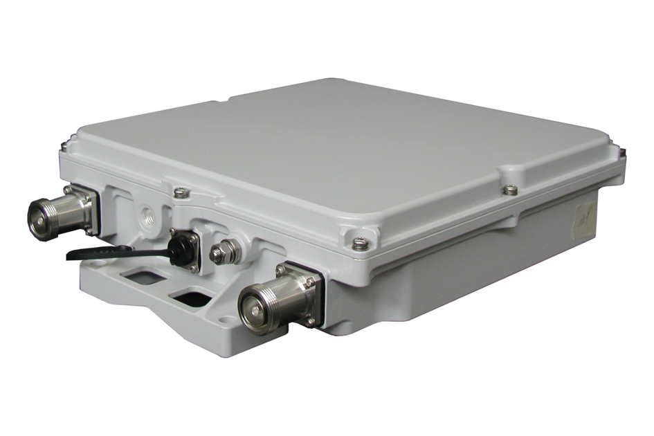
Tower Mounted Amplifier, Dual LTE 800 with AISG
Specifications
Specifications
Product Classification
| Product Type | 1-BTS:1-ANT (Uniplex) | Tower mounted amplifier |
General Specifications
| Color | Gray |
| Modularity | 2-Twin |
| Mounting | Pole | Wall |
| Mounting Pipe Hardware | Band clamps (2) |
| RF Connector Interface | 7-16 DIN Female |
| RF Connector Interface Body Style | Long neck |
Dimensions
| Height | 299 mm | 11.772 in |
| Width | 295 mm | 11.614 in |
| Depth | 79 mm | 3.11 in |
| Ground Screw Diameter | 8 mm | 0.315 in |
| Mounting Pipe Diameter Range | 50–120 mm |
Outline Drawing
| Click on image to enlarge. |

Electrical Specifications
| License Band, LNA | EDD 800 |
Electrical Specifications, dc Power/Alarm
| dc Switching/Redundancy | Yes |
| Lightning Surge Current | 3 kA |
| Lightning Surge Current Waveform | 10/350 waveform |
| Operating Current at Voltage | 135 mA @ 12 Vdc |
| Operating Current Tolerance | ±15 mA |
| Voltage | 7–30 Vdc |
| Voltage, CWA Mode | 7–18 Vdc |
| Alarm Current, CWA Mode | 185 mA ±15 mA |
Electrical Specifications, AISG
| AISG Connector | 8-pin DIN Female |
| AISG Connector Standard | IEC 60130-9 |
| Default Protocol | AISG 2.0 |
| Protocol | AISG 1.1 | AISG 2.0 |
| Voltage, AISG Mode | 10–30 Vdc |
Electrical Specifications
| Sub-module | 1 | 2 |
| Branch | 1 |
| Port Designation | ANT |
| License Band | EDD 800, LNA |
Electrical Specifications, Rx Uplink
| Frequency Range, MHz | 832–862 |
| Bandwidth, MHz | 30.00 |
| Gain, nominal, dB | 12.0 |
| Gain Tolerance, dB | ±1 |
| Noise Figure, maximum, dB | 1.6 |
| Noise Figure, typical, dB | 1.5 |
| Group Delay Variation, maximum, ns | 80 |
| Group Delay Variation Bandwidth, MHz | 5.00 |
| Total Group Delay, maximum, ns | 120 |
| Output IP3, minimum, dBm | 10 |
| Return Loss, minimum, dB | 18 |
| Insertion Loss - Bypass Mode, typical, dB | 1.8 |
| Return Loss - Bypass Mode, typical, dB | 14 |
| TX Band Rejection, minimum, dB | 80 |
Electrical Specifications, Tx Downlink
| Frequency Range, MHz | 791–821 |
| Bandwidth, MHz | 30.00 |
| Insertion Loss, maximum, dB | 0.60 |
| Insertion Loss Ripple, maximum, dB | 0.25 |
| Group Delay Variation, maximum, ns | 25 |
| Group Delay Variation Bandwidth, MHz | 5.00 |
| Total Group Delay, maximum, ns | 70 |
| Return Loss, minimum, dB | 18 |
| RX Band Rejection, minimum, dB | 45 |
| Input Power, RMS, maximum, W | 160 |
| Input Power, PEP, maximum, W | 2,500 |
| 3rd Order PIM, maximum, dBc | -158 |
| 3rd Order PIM Test Method | Two +43 dBm carriers |
Block Diagram
| Click on image to enlarge. |

Material Specifications
| Finish | Painted |
Mechanical Specifications
| Wind Loading @ Velocity, maximum | 55.0 N @ 115 km/h (12.4 lbf @ 115 km/h) |
| Wind Speed, maximum | 198 km/h (123 mph) |
Environmental Specifications
| Operating Temperature | -40 °C to +65 °C (-40 °F to +149 °F) |
| Relative Humidity | Up to 100% |
| Corrosion Test Method | IEC 60068-2-11, 30 days |
| Ingress Protection Test Method | IEC 60529:2001, IP67 |
Packaging and Weights
| Included | Mounting hardware |
| Volume | 7 L |
| Weight, net | 9.4 kg | 20.723 lb |
Regulatory Compliance/Certifications
| Agency | Classification |
| ISO 9001:2015 | Designed, manufactured and/or distributed under this quality management system |
Product Classification
| Product Type | 1-BTS:1-ANT (Uniplex) | Tower mounted amplifier |
General Specifications
| Color | Gray |
| Modularity | 2-Twin |
| Mounting | Pole | Wall |
| Mounting Pipe Hardware | Band clamps (2) |
| RF Connector Interface | 7-16 DIN Female |
| RF Connector Interface Body Style | Long neck |
Dimensions
| Height | 299 mm | 11.772 in |
| Width | 295 mm | 11.614 in |
| Depth | 79 mm | 3.11 in |
| Ground Screw Diameter | 8 mm | 0.315 in |
| Mounting Pipe Diameter Range | 50–120 mm |
Electrical Specifications
| License Band, LNA | EDD 800 |
Electrical Specifications, dc Power/Alarm
| dc Switching/Redundancy | Yes |
| Lightning Surge Current | 3 kA |
| Lightning Surge Current Waveform | 10/350 waveform |
| Operating Current at Voltage | 135 mA @ 12 Vdc |
| Operating Current Tolerance | ±15 mA |
| Voltage | 7–30 Vdc |
| Voltage, CWA Mode | 7–18 Vdc |
| Alarm Current, CWA Mode | 185 mA ±15 mA |
Electrical Specifications, AISG
| AISG Connector | 8-pin DIN Female |
| AISG Connector Standard | IEC 60130-9 |
| Default Protocol | AISG 2.0 |
| Protocol | AISG 1.1 | AISG 2.0 |
| Voltage, AISG Mode | 10–30 Vdc |
Electrical Specifications
| Sub-module | 1 | 2 |
| Branch | 1 |
| Port Designation | ANT |
| License Band | EDD 800, LNA |
Electrical Specifications, Rx Uplink
| Frequency Range, MHz | 832–862 |
| Bandwidth, MHz | 30.00 |
| Gain, nominal, dB | 12.0 |
| Gain Tolerance, dB | ±1 |
| Noise Figure, maximum, dB | 1.6 |
| Noise Figure, typical, dB | 1.5 |
| Group Delay Variation, maximum, ns | 80 |
| Group Delay Variation Bandwidth, MHz | 5.00 |
| Total Group Delay, maximum, ns | 120 |
| Output IP3, minimum, dBm | 10 |
| Return Loss, minimum, dB | 18 |
| Insertion Loss - Bypass Mode, typical, dB | 1.8 |
| Return Loss - Bypass Mode, typical, dB | 14 |
| TX Band Rejection, minimum, dB | 80 |
Electrical Specifications, Tx Downlink
| Frequency Range, MHz | 791–821 |
| Bandwidth, MHz | 30.00 |
| Insertion Loss, maximum, dB | 0.60 |
| Insertion Loss Ripple, maximum, dB | 0.25 |
| Group Delay Variation, maximum, ns | 25 |
| Group Delay Variation Bandwidth, MHz | 5.00 |
| Total Group Delay, maximum, ns | 70 |
| Return Loss, minimum, dB | 18 |
| RX Band Rejection, minimum, dB | 45 |
| Input Power, RMS, maximum, W | 160 |
| Input Power, PEP, maximum, W | 2,500 |
| 3rd Order PIM, maximum, dBc | -158 |
| 3rd Order PIM Test Method | Two +43 dBm carriers |
Material Specifications
| Finish | Painted |
Mechanical Specifications
| Wind Loading @ Velocity, maximum | 55.0 N @ 115 km/h (12.4 lbf @ 115 km/h) |
| Wind Speed, maximum | 198 km/h (123 mph) |
Environmental Specifications
| Operating Temperature | -40 °C to +65 °C (-40 °F to +149 °F) |
| Relative Humidity | Up to 100% |
| Corrosion Test Method | IEC 60068-2-11, 30 days |
| Ingress Protection Test Method | IEC 60529:2001, IP67 |
Packaging and Weights
| Included | Mounting hardware |
| Volume | 7 L |
| Weight, net | 9.4 kg | 20.723 lb |
| Click on image to enlarge. |
| Click on image to enlarge. |
Regulatory Compliance/Certifications
| Agency | Classification |
| ISO 9001:2015 | Designed, manufactured and/or distributed under this quality management system |
Documentation & Downloads
Installation Instruction
Product Specification
Video
Filter Products – Designed for PIM Excellence

Filter Products – Designed for PIM Excellence
Warranty
Installation Instruction
Product Compliance Documentation
Product Specification
Video
Filter Products – Designed for PIM Excellence
Filter Products – Designed for PIM Excellence
Warranty
Other Ways to Browse
