Whitepaper: Hochgeschwindigkeitsmigration
Hochgeschwindigkeitsmigration in Rechenzentren: Infrastrukturprobleme, Trends, Hauptantriebskräfte und Empfehlungen
Im Rechenzentrum ist Geschwindigkeit alles. The challenge is to look ahead and know what you have to be prepared to deliver—in the immediate future and later on—and chart the most expedient and flexible course forward. The faster that available technologies and applicable standards evolve, the harder that job becomes.
Recent data center trends continue to predict 25 to 35 percent annual growth in data-center traffic and bandwidth requirements. This demand for more network capacity can only be supported by a shift to higher switching speeds, which is precisely what is now happening in the market. According to Dell’Oro Group, shipments of 25 Gbps and 100 Gbps ports increased to more than one million in the first quarter of 2017. Dell’Oro predicts Ethernet switch revenue will continue to grow through the end of the decade, with a large share allocated to 25G and 100G ports.1
Migration strategies are evolving as well. The growing affordability of 100G switch links—multimode and singlemode—is enabling many companies to update their switch networks from 10G directly to 100G, skipping 40G altogether. The shift to 25G lanes is well underway as well, with 25G-lane switches becoming more commonplace.
Looking ahead, lane capacities are expected to continue doubling, reaching 100G by 2020 and enabling the next generation of high-speed links for fabric switches.
A number of factors are driving the surge in data center throughput speeds.
- Server densities are increasing by approximately 20 percent a year.
- Processor capabilities are growing, with Intel recently announcing a 22-core processor.
- Virtualization density is increasing by 30 percent2, which is driving the uplink speeds to switches.
- East-west traffic in the data center has far surpassed the volume of north-south traffic3.
“The idea going forward is to push lanes to 25 Gb/sec speeds, as the current crop of Ethernet switches are doing, and then ramp up to 50 Gb/sec lanes and then 100 Gb/sec lanes and keep the lane count down around eight.” — The Next Platform, März 2016
The network design has to reflect this massive amount of traffic, and, importantly, has to allow for server, storage and network capacity to all be scaled up independently and with as little disruption and reconfiguration as possible. As a result, data center professionals must support higher server densities, deploy more fiber and accelerate plans to migrate to higher speeds in their core and aggregation networks. The network infrastructure within the data center must be able to scale to support these significant changes.
“Adoption of network architectures such as spine and leaf… are driving not only bandwidth demand, but also the scale of the network, requiring a greater fiber count for the cabling infrastructure.” — Data Center Journal, 25. April 2016
Changing network architecture
The change in data center traffic and direction requires a network design that accommodates the rapid increase of east-west data traffic. The traditional data center architecture used a three-layer topology (Figure 1). The core layer, typically located in the main distribution area (MDA), connects the various network switches to each other and to network sources outside the data center.
Abbildung 1: Traditional three-layer topology
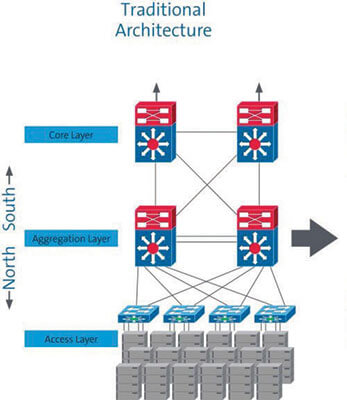
The core layer feeds the aggregation layer, connecting the various access switches. In large enterprise and cloud data centers, the aggregation layer is usually located in the intermediate distribution area (IDA). In smaller facilities, it is typically the horizontal distribution area (HDA) or equipment distribution area (EDA). The access network connects storage and compute resources in the data center.
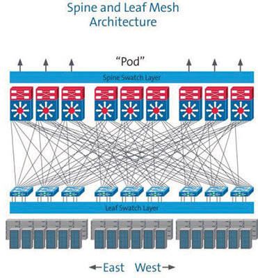
The design of this model provides a predictable foundation for a scalable data center network but is less than ideal when it comes to supporting today’s low-latency, virtualized applications. As a result, there has been a swift and dramatic shift to the “leaf-and-spine” architecture (Figure 2). The leaf-and-spine model is optimized to move data in an east-west flow, enabling servers to co-operate in delivering cloud-based applications. In this topology, networks are spread across multiple leaf-and- spine switches, making the leaf-and-spine switch layer critical for delivering maximum scale and performance.
Each leaf switch is connected to every spine switch, creating a highly resilient any-to-any structure. The mesh of fiber links creates a high-capacity network resource or “fabric” that is shared with all attached devices. All fabric connections run at the same speed. The higher the speed, the higher the capacity of the mesh network, often called a “fabric network.”
Fabric networks require a large number of fiber connections, particularly in the leaf-switch layer. Equipment vendors continuously work to increase the density of their line cards in order to keep pace. With the increasing density, cabling connectivity and management become more important.
Fabric networks require high-speed links across the entire mesh, which often spans the entire data center. Deploying more links with higher speeds and longer reach has become the new normal for physical network designs.
Abbildung 2: Two-layer spine-leaf
Evolving standards
Applications standards organizations, namely the IEEE 802.3 (Ethernet) and ANSI/T11 (Fibre Channel Committees) have been busy updating the recommended guidelines in order to keep pace with the rapid increases in bandwidth. The objective of these standards groups is not just to facilitate the evolution to ever-increasing line rates; they also encourage development of higher-speed applications that will increase the cost effectiveness of links between the data center equipment. To this end, a number of intermediate speeds are being developed to fill the gap between 10G, 40G, 100G and 400G. Table 1 lists the various Ethernet standards. Those still in process are highlighted in purple.
Table 1— IEEE 802.3 Ethernet fiber standards—completed and in progress (PURPLE)
|
Anwendung |
Standard |
IEEE reference |
Medien |
Geschwindigkeit |
Target distance |
|
10-Gigabit Ethernet |
10GBASE-SR |
802.3ae |
MMF |
10 Gb/s |
33 m (OM1) to 550 m (OM4) |
|
10GBASE-LR |
SMF |
10 km |
|||
|
10GBASE-LX4 |
MMF |
300 m |
|||
|
10GBASE-ER |
SMF |
40 km |
|||
|
10GBASE-LRM |
802.3aq |
MMF |
220 m (OM1/OM2) to 300 m (OM3) |
||
|
25-Gigabit Ethernet |
25GBASE-SR |
P802.3by |
MMF |
25 Gb/s |
70 m (OM3) 100 m (OM4) |
|
40-Gigabit Ethernet |
40GBASE-SR4 |
802.3bm |
MMF |
40 Gb/s |
100 m (OM3) 150 m (OM4) |
|
40GBASE-LR4 |
SMF |
10 km |
|||
|
40GBASE-FR |
SMF |
2 km |
|||
|
40GBASE-ER4 |
SMF |
40 km |
|||
|
100-Gigabit Ethernet |
100GBASE-SR10 |
MMF |
100 Gb/s |
100 m (OM3) 150 m (OM4) |
|
|
100GBASE-LR4 |
SMF |
10 km |
|||
|
100GBASE-SR4 |
SMF |
70 m (OM3) 100 m (OM4) |
|||
|
100GBASE-ER4 |
SMF |
40 km |
|||
|
50Gm 100G and 200G |
50GBASE-SR |
802.3cd |
MMF |
50 Gb/s |
100 m (OM4) |
|
Ethernet |
SMF |
2 km |
|||
|
50GBASE-LR |
SMF |
10 km |
|||
|
100GBASE-SR2 |
MMF |
100 Gb/s |
100 m (OM4) |
||
|
100GBASE-DR2 |
SMF |
500 m |
|||
|
100GBASE-FR2 |
SMF |
2 km |
|||
|
200GBASE-SR4 |
MMF |
200 Gb/s |
100 m (OM4) |
||
|
200-Gigabit Ethernet |
200GBASE-DR4 |
P802.3bs |
SMF |
500 m |
|
|
200GBASE-FR4 |
SMF |
2 km |
|||
|
200GBASE-LR4 |
SMF |
10 km |
|||
|
400-Gigabit Ethernet |
400GBASE-SR16 |
MMF |
400 Gb/s |
70 m (OM3) 100 m (OM4) |
|
|
400GBASE-DR4 |
SMF |
500 m |
|||
|
400GBASE-FR8 |
SMF |
2 km |
|||
|
400GBASE-LR8 |
SMF |
10 km |
Options for migration
The discussion surrounding migration to higher line rates is both complex and rapidly evolving. It includes a wide range of decisions regarding fiber type, modulation and transmission schemes, connector configurations and, of course, cost considerations. Figure 4 shows a possible migration path, but there are many others. Determining which one is best for any given environment means carefully considering each aspect. The following are just a few of the many issues that must be weighed.
Abbildung 4: 40GBASE-SR4 link with parallel optics in switch and server

40G or 25G lanes?
Until recently, the accepted migration road map outlined a predicted jump from 10G lanes to 40G. Since approval of the IEEE 802.3by standard, the industry has shifted to 25G lanes as the next switching technology. This is largely due to the fact that the newer 25G lanes offer easy migration to 50G (2x25G) and 100G (4x25G), and, to a lesser extent, improved utilization of the switching silicon in network switches. Using a network port at 25G vs 10G provides more capacity for the same capital and operating costs. 25G lanes also enable a clean and logical grouping for support of 100G, 200G and 400G speeds.
Modulationsschemata
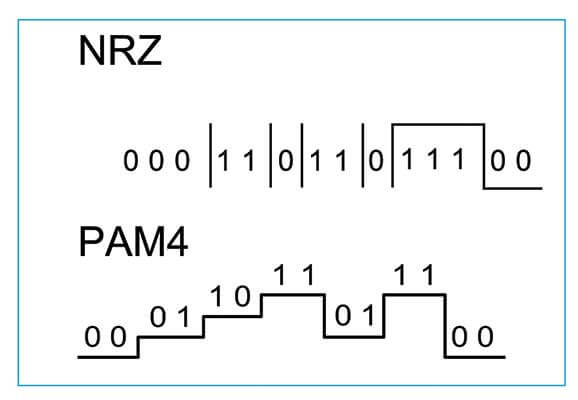
New, more efficient modulation schemes are also now available. Pulse-amplitude modulation with four amplitude levels (PAM-4) has been proposed for optical links, both within the data center and among multiple data center facilities. As shown in Figure 5, PAM-4 uses four distinct pulse amplitudes to transmit data. Compared to traditional NRZ, PAM-4 enables twice the transmission capacity at the same signaling rate. The downside, however, is that it requires a higher signal- to-noise ratio (SNR), which puts stricter requirements on the supporting physical infrastructure. Still, its simplicity and low power consumption make PAM-4 one of the most promising modulation techniques for 100G and beyond.
Abbildung 5: 6-4 and NRZ modulation
Transceiver technology
In addition to more advanced modulation schemes to increase channel speeds, various wavelength division multiplexing (WDM) techniques are being developed to increase the number of wavelengths transmitted on each fiber. WDM has been used for more than two decades to increase data rates on long-haul networks by reducing fiber counts. It has also been used in singlemode Ethernet applications, such as 10GBASE-LR4 and 100GBASE-LR4, which combine four wavelengths on the same fiber using coarse WDM technology. This concept has also been extended to multimode fiber using a technique known as shortwave WDM or SWDM. As shown in Figure 6, SWDM utilizes wavelengths from 850 nm to 940 nm.
Abbildung 6: SWDM combining four wavelengths from 850 nm to 940 nm

Serial or parallel transmission?
As more demanding applications drive data rates higher, the market is also gravitating to parallel optics. This trend is supported by the consistent demand for MPO-based trunks, a data center staple for more than a decade. Using laser-optimized multimode fiber (LOMMF), serial optics can cost-effectively support speeds up to 10G. Historically, using serial transmission to support 25G or 40G required switching to costlier singlemode transceivers. Parallel optics, however, provide a cost-effective solution for migrating to 40G and allows the grouping of 25G lanes to deliver 100G. Meanwhile, future paths are being established for 200/400G Ethernet on both singlemode and multimode fiber using a combination of serial and parallel transmission.
The switch to parallel optics is being accelerated by the increasing use of MPO connectors. In North America, sales of 40/100GbE MPO connectors are forecast to increase 15.9 percent annually through 2020, reaching $126 million in 2020.4 However, the trend to parallel optics may ebb and flow as new technologies are implemented that make better use of duplex pairs.
Meanwhile, duplex 100G applications using four 25G lanes are being driven by cost-effective technologies such as SWDM4. In the near future, 50G PAM-4 lanes will also provide 100G over multimode fiber. Both SWDM4 and PAM-4 enable additional savings, as they require fewer fibers than an equivalent parallel optic system.
Figure 6a: Short reach 100G applications in the data center
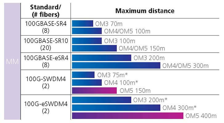
* OM3/OM4 effective modal bandwidth only specified at 850nm
Preterminated vs field-terminated cables
The need to turn up networking services quickly has increased the value and demand for preterminated cabling systems. By some estimates, the plug-and-play capability of preterminated cables translates to 90 percent time savings versus a field- terminated system and are about 50 percent faster when it comes to network maintenance.5 The value grows as the number of fiber connections within the network increases. Factory-terminated systems are also the only viable solution to the extremely low-loss systems that are required to support high-speed optic links. Among preterminated solutions, MPO fiber is the de-facto system for both singlemode and multimode connectivity due to its high performance, ease of use, deployment speed and cabling density.
Singlemode or multimode
One of the most complex decisions facing data center managers is when and where to deploy singlemode or multimode links. The affordability of pluggable singlemode optics continues to improve, enabling 100G Ethernet to capture a large share of the data center switch port market. This is true of both hyperscale and enterprise data centers.
But the conversation regarding the three transmission types must go well beyond the cost of pluggable optics. It should include an analysis of total channel cost, as well as the anticipated growth of the data center and its migration road map. The following are a few of the issues that should be considered and thoroughly understood prior to any decision.
Abbildung 7: Single link cost comparison
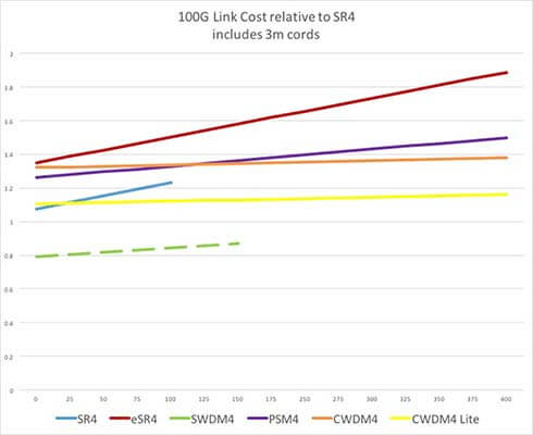
Abbildung 8: Estimating appropriate channel length based on topology.
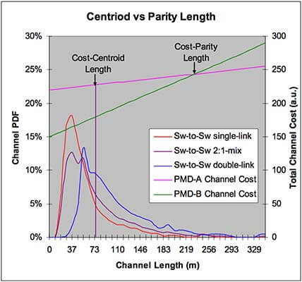
Quelle: IEEE 802.3 Next Gen 40G and 100G Optics Study Group;
Mai 2012
Link distances: Data centers generally require a large number of network links with relatively short distances. This makes lower cost multimode more attractive, but only if it can support the speeds that will be required as the network evolves. Singlemode, on the other hand, is commonly used in data center entrance facilities and its long-distance capabilities make it the only choice for links between data centers and metro/wide area networks. In fact, many long- reach, high-speed options are only available in singlemode.
Network topology: Some data centers may have over 100,000 servers while others may have just a few. Some use a centralized placement of network equipment while others distribute networking equipment throughout the data center. These design requirements and choices determine the number of network links and the distance that the network links must support.
Total channel cost: Comparing link costs between network types involves assessing the cost of the entire link— transceivers, trunks and patch cords. A variety of costing models have been developed to help compare the relative cost of different network link types. Some of these models, such as the one illustrated in Figure 8, provide guidance on the appropriate link lengths based on the topology selected and are useful when the average link-length is unknown. For example, the model indicates that the relative costs of the PMD channels A and B are equal at a length of approximately 230 meters. Therefore, knowing the link length enables us to determine the lower-cost solution.
When the average channel length is known, making an accurate cost comparison between link types is easier. Using data resources such as the chart in Figure 7, the process of evaluating relative total channel costs is fairly straightforward. Figure 7 compares the costs (transceivers, trunks and patch cords) of various 100GBASE links, from 50 to 300 meters in length. This model also compares 100GBASE-SWDM4 duplex optics with OM5 cabling to 100GBASE-SR4 using OM4. Among other things, it shows that the SWDM option provides a much lower capital cost. Because SWDM uses OM5 it enables extended 100G support on multimode fiber. The recent announcement of 100G eSWDM4 to 400m on OM5 now rivals that of short reach SM DC optics like PSM4.
While the cost of any link is length-dependent, some have an inherently higher cost due to an increased number of fibers, and this difference must be accounted for in the comparison. It is also important to understand that tools such as those shown in Figures 7 and 8 apply to enterprise data centers. They cannot, however, be used reliably to compare link costs within a hyperscale environment. This is due to the extreme size and bandwidth requirements of these facilities.
Other considerations: In many cases, the channel distance may be so short that length is not the critical variable determining cost. In these instances, the decision regarding the best transmission medium typically comes down to one or more of the following factors.
- Link Speeds: Every data center facility will (or should) have its own migration roadmap, based on the anticipated IT needs of the organization and the infrastructure evolution needed to support it. The transmission medium must be able to support the maximum link speed for the current and future applications.
- Channel OpEx: Operational costs should include an evaluation of the personnel, process and vendor relations necessary to support the transmission medium being considered. The extensive capabilities and complexities of each technology have led to the specialization of skills, fluency in standards and other core competencies. Launching a new transmission medium, without having the requisite resources to manage it, invites increased risk and additional costs.
- Infrastructure life cycle: Ideally, the infrastructure would be able to support multiple generations of equipment technology in order to avoid a costly rip-and-replace.
OM4 or OM5 (wideband)
Within the multimode landscape, data center operators are faced with yet another set of complex decisions regarding which multimode technology to deploy. The choice involves OM3, OM4 and OM5 wideband.
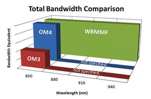
Abbildung 9: Total bandwidth comparison
OM3 laser optimized fiber, was introduced primarily developed to support 10GbE links. It was standardized in 2002 and its successor, OM4, was standardized in 2009. Both multimode fibers are optimized for VCSEL transceivers operating at 850 nm and both use identical connectors. OM4, however, improves attenuation and bandwidth over OM3.
For OM3 the maximum attenuation is <3.5 dB/Km but, for OM4 propagation, loss improves to <3.0 dB/Km. As a result, OM4 can support greater distances and increased throughput.
The real decision, then, is between OM4 and OM5. Introduced by CommScope in 2015, OM5 was recently approved under ANSI/TIA-492AAAE and is recommended by ANSI/TIA-942-B. A significant plus for OM5 is it enhances the ability of short-wavelength division multiplexing (SWDM) to span longer distances. It also enables data center operators to reduce parallel fiber counts by at least a factor of four. This means that, to support 40 Gbps and 100 Gbps lanes, two OM5 fibers can do the job of eight OM4 fibers. Figure 9 shows a bandwidth comparison between OM3, OM4 and OM4 wideband fibers. Additionally, OM5 supports all legacy multimode applications and is compatible with OM3 and OM4 fiber. As WDM and PAM-4 technologies continue to develop, the ability of OM5 to support SWDM will enable the technology to separate itself from legacy multimode fibers.
Intelligent systems
Automated infrastructure management (AIM) systems can greatly assist in the migration process by providing an accurate mapping of the physical layer and all connected devices. Because AIM systems automatically monitor and document all ports and fibers in use, they can help ensure capacity is available when upgrading from duplex to parallel.
Additionally, AIM can help identify surplus cabling and switch ports and make them available for parallel-to-duplex migration. Capabilities such as these have been articulated in the ISO/IEC 18598 standard and the European Standard EN 50667 for AIM, both ratified in 2016. The benefits of deploying an AIM-based system are also echoed by TIA as the organization drafts the ANSI/TIA-5048 standard, which repeats, nearly verbatim, the language used in the ISO/IEC 18598 standard.
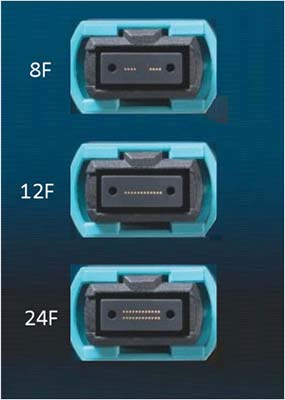
Abbildung 10: MPO connectors with varying fiber counts
The CommScope view
In evaluating the options and market trajectory, the following recommendations represent CommScope’s take on some of the issues discussed in this paper:
- Preterminated MPO-based fiber solutions will continue to be the optimal choice for high-performance networks. They provide excellent factory-terminated performance, plus the speed and agility to support the expansion requirements of private, cloud-like enterprise data centers.
- SYSTIMAX® ultra low-loss (ULL) singlemode and multimode fiber trunks and cabling assemblies will greatly enhance the support for high-speed applications while maintaining the flexibility to support TIA 942–B structured cabling designs.
- MPO 12-fiber systems, which have been deployed for years, will continue to be used in support of duplex and parallel applications. Improved ULL performance will offer excellent flexibility in deployment and reach for most data center applications and provide solid operational uniformity. Expect use of MPO 12-fiber systems to continue as future applications emerge.
- For high-capacity, high-density applications we advocate for the use of MPO 24-fiber multimode systems. As spine-and- leaf architectures continue to mature, MPO 24-fiber enables the increase in density and capacity for growing duplex multimode networks. Another advantage is that MPO24 provides agile support for 8-fiber parallel applications.
- Finally, we anticipate selective use of MPO 8-fiber systems. This includes use in popular four-lane QSFP applications with 4X10G or 4X25G configurations, primarily for storage and server network attachments. Because network fabric links do not require breakouts to lower-speed ports, two-fiber duplex links, such as 100G SWDM4, can be an attractive choice for switch-to-switch links.
Whatever your choice, CommScope’s solutions support 8-, 12- and 24-fiber parallel and two-fiber duplex applications offering the optimal support for a broad array of data center applications.
A closing thought
While it is important to understand the vast array of technical options and emerging solutions, these must be viewed within the context of your specific enterprise data center environment. What is the trajectory of the enterprise? How does that affect the velocity of change and scaling requirements in the data center? What is the total cost of ownership for the various migration scenarios being considered?
As a data center manager, remember, you don’t have to go it alone. The amount of research and decisions involved can be mind-numbing. There are various knowledgeable resources, such as CommScope, that have the solutions and experience to help you make the right decision. By leveraging our technical expertise and broad perspective, together we can help you develop a long-term migration strategy designed to keep your data center adaptable, capable and efficient. No matter how fast things change. We have a vision for the future and the expertise to get you there.
Quellen
1 Construction Zones on the Ethernet Roadmap; The Next Platform; 24. März 2016
2 Data Center Strategies North American Enterprise Survey; Infonetics Research; Mai 2015
3 Facebook Gives Lessons in Network-Datacenter Design; November 2014
4 Market Forecast—MPO Connectors in 40/100GbE; ElectroniCast Consultants; Dezember 2015
5 Weighing the costs and benefits of preterminated fiber-optic systems; Cabling Installation & Maintenance; 01. Mai 2014

