Produktart

Sie können Produkte auch nach Netzwerktyp anzeigen
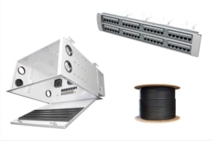
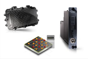 Breitband und Zugangsnetzwerksysteme
Die hochmodernen Zugangsnetzwerksysteme von CommScope für Breitbandverbindungen.
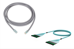 Kabelbausätze
Liefern Sie optimale Hochgeschwindigkeitsleistung mit einer Vielzahl von Kabelbaugruppen, einschließlich Kupfer-, Glasfaser- und Hybridoptionen.
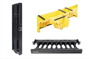 Kabelmanagement
Sorgen Sie mit diesen Kabelmanagement-Optionen für Ordnung in Ihren Rechenzentren, gebäudeinternen Durchgängen und Telekommunikationsschränken.
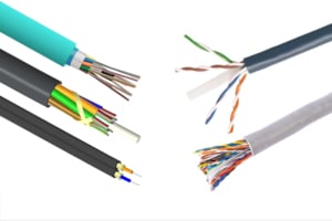 Kabel
Kabel
Die Hochleistungskabel von CommScope sorgen für minimale Signalverluste und maximale Bandbreiten. Entdecken Sie noch heute unser umfangreiches, vielseitiges Portfolio.
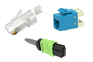 Kupplungen
Entdecken Sie zuverlässige Kupfer- und Glasfaseranschlüsse und vieles mehr. Leistungsstarke Optionen vereinfachen die Installation für eine überragende Konnektivität
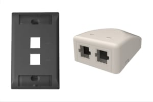 Blenden und Boxen
Die Blenden und Boxen von CommScope erfüllen technische und funktionale Anforderungen und berücksichtigen zugleich die Ästhetik an der Frontseite Ihrer Kupfer- und Glasfasernetze.
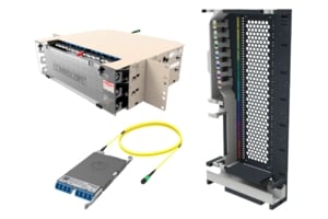 Rahmen, Panele, Kassetten und Module
Rahmen, Panele, Kassetten und Module gewährleisten einen exzellenten Schutz sowie maximale Zuverlässigkeit und Skalierbarkeit für Ihre Inhouse-Netzwerke.
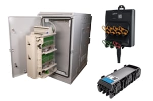 Knotenpunkte, Verschlüsse, Terminals und Boxen
Knotenpunkte, Verschlüsse, Terminals und Boxen gewährleisten einen exzellenten Schutz sowie maximale Zuverlässigkeit und Skalierbarkeit für Ihre Netzwerke im Außenbereich.
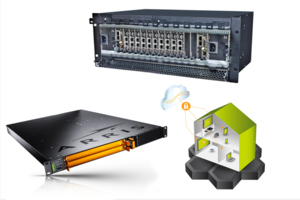
 Netzwerksysteme
Implementieren, organisieren und verwalten Sie die Daten- und Stromverteilung, im Innen- und Außenbereich.
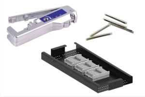 Werkzeuge und Zubehör
Nutzen Sie Tools und Zubehör, die Installationen im Innen- und Außenbereich sowie Wartung schnell und einfach machen.
 Videoverarbeitung, Sicherheit und Bereitstellungssysteme
Liefern Sie qualitativ hochwertige Videoservices über HFC und Kabelnetze.