Author

Earl Parsons
Categories
Data Center Venue & Campus NetworksIf data centers are to continue satisfying the world’s hunger for more data-hungry applications and services, the industry needs to figure out how to pump more bytes through the network while holding the line on energy consumption.
Co-packaged optics (CPO) seeks to mitigate the power consumption issue by placing the optical engine and ASIC on the same substrate as a single packaged assembly. Done right, CPO would not only reduce power requirements; it could also help data centers improve port density, thermal management, and bandwidth.
Co-packaged optics is seen by many as the next evolutionary step in data center switches. The Optical Internetworking Forum (OIF) has several projects related to co-packaged optics. The Consortium for On-Board Optics recently release a white paper: “Design Considerations of Optical Connectivity in a Co-Packaged or On-Board Optics Switch.”
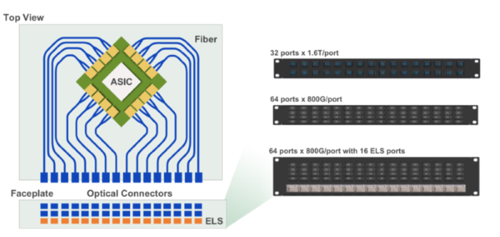
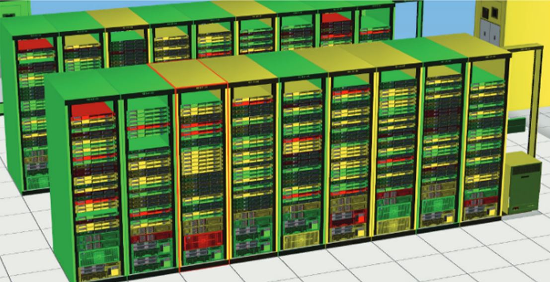
Source: “Design Considerations of Optical Connectivity in a Co-Packaged or On-Board Optics Switch”
One cloud data center operator recently announced that they would deploy 25.6 T switches with co-packaged optics.
In traditional data center switches, the switch ASIC (application specific integrated circuit) sits in the center of the switch and handles all the packet routing. Electrical traces on a printed circuit board connect the switch ASIC to the cages on the switch front panel. Pluggable optical transceivers are then inserted into the cages and fiber cables connect transceivers in different switches across the data center.
As data rates increase, data center power consumption becomes a major concern to operators. 200G electrical lanes will consume a significant amount of power to traverse the distance between the switch chip and the switch front panel. Co-packaged optics seek to mitigate this power consumption by moving the optical transmit and receive functions closer to the switch chip. Optical fiber would then carry the signals to the front panel, where optical cables would connect directly on the front panel.
The switch from pluggable optics to co-packaged optics leads to important considerations for fiber-optic cabling. With pluggable optics, the fiber cable is plugged into the medium-dependent interface (MDI). Ethernet standards define test point 2 (TP2) as the output of a two-meter fiber cable connected to the MDI. All optical transmit parameters are defined at TP2, not at the output of the MDI. To ensure interoperability with pluggable module standards, the co-packaged optics TP2 needs to be in the same place. Parameters like transmit power and optical modulation amplitude should be measured after a two-meter fiber cable connected to the switch front panel. Any connector loss from the front panel connection needs to be compensated with increased laser transmit power; it cannot be lumped with the cable plant power budget.
Likewise, TP3 with pluggable modules is defined as the output of the fiber cable that connects to the receiver MDI. This needs to be maintained in co-packaged systems. Any connector loss from the front panel connection needs to be compensated with improved receiver sensitivity.
Most co-packaged switch designs use silicon photonics. Light from an external laser is coupled into the silicon photonics chip, which uses external modulators to encode data on the light. The optical signal is then launched into an optical fiber and carried to the front panel. The external lasers must operate at a high level to compensate for the losses on the silicon photonics chip—losses that could be up to 12 decibels. This increase in laser power offsets the power savings of co-packaged optics.
Another concept promises even lower power usage. Co-packaged optics using VCSELs coupled to multimode fiber could operate up to 100 meters with very lower power usage. IEEE 802.3db recently standardized the usage of 100G VCSELs up to four lanes, and IEEE 802.3df will extend this to eight lanes for 800G. Co-packaged optics using VCSELs and multimode fiber have the potential for low-cost, low-power (but high-volume) switches.
With co-packaged optics switches, the front panel density story changes. Traditional switches are limited in density by the size of OSFP or QSFP-DD transceivers. Co-packaged switches can offer higher density where the front panels have only fiber connectors, which are smaller than transceivers. Well-established connectors like MPO—as well as new very small form factor (VSFF) connectors like SN-MT and MMC—offer the greatest density potential. MPO16 will see wide use in co-packaged switches as the fiber bundles coming from the co-packaged chiplets are divisible by 16, but not by 12.
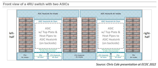
The pluggable transceiver industry has their own solutions to the power problems of future high-speed transceivers. The switch to thin film lithium niobate modulators in pluggable transceivers may provide a similar power savings to co-packaged optics. Another concept presented at ECOC 2022 flips the ASIC board in a 2 RU switch sideways and uses short electrical traces to the OSFP cages on the front of the switch (see figure below).
Co-packaged optics represent a new switch technology. The concepts outlined above should be considered to ensure co-packaged switches are interoperable with existing pluggable optics to enable broad adoption.