CDX623T-DS-T | E15V95P63
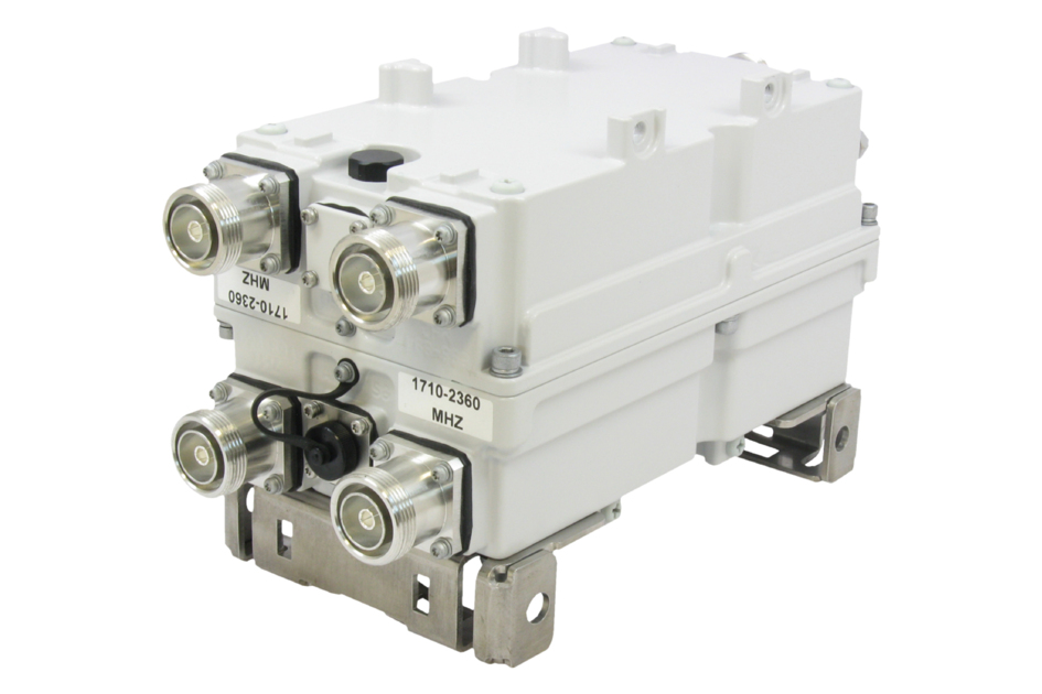
Twin Diplexer,555–894 MHz/1695–2360 MHz, dc sense, LOC-top
Specifications
Features and Benefits
- Automatic dc switching with dc sense
- dc redundancy with dummy current sink
- Integrated layer one converter (AISG modem)
- Convertible mounting brackets
- Stackable to single unit with included hardware
- Stackable in multiples with included hardware
- Feeder-to-antenna application
Specifications
Product Classification
| Product Type | Diplexer |
General Specifications
| Product Family | CDX623 |
| Color | Gray |
| Common Port Label | Common |
| Modularity | 2-Twin |
| Mounting | Frame | Pole | Rack | Rod | Wall |
| Mounting Pipe Hardware | Band clamps (2) |
| RF Connector Interface | 7-16 DIN Female |
| RF Connector Interface Body Style | Medium neck |
Dimensions
| Height | 225 mm | 8.858 in |
| Width | 126 mm | 4.961 in |
| Depth | 115 mm | 4.528 in |
| Ground Screw Diameter | 8 mm | 0.315 in |
| Mounting Pipe Diameter Range | 40–160 mm |
Outline Drawing
| Click on image to enlarge. |

Electrical Specifications
| Impedance | 50 ohm |
| License Band, Band Pass | APT 700 | AWS 1700 | CEL 850 | DCS 1800 | EDD 800 | IMT 2100 | LMR 750 | LMR 800 | PCS 1900 | USA 700 | USA 750 | WCS 2300 |
Electrical Specifications, dc Power/Alarm
| dc/AISG Pass-through Method | Auto sensing |
| dc/AISG Pass-through Path | See logic table |
| Lightning Surge Current | 10 kA |
| Lightning Surge Current Waveform | 8/20 waveform |
| Operating Current at Voltage | 35 mA @ 12 V | 37 mA @ 24 V |
| Voltage | 10–30 Vdc |
Electrical Specifications, AISG
| AISG Carrier | 2176 KHz ± 100 ppm |
| AISG Connector | 8-pin DIN Female |
| AISG Connector Standard | IEC 60130-9 |
| Insertion Loss, maximum | 0.5 dB |
| Return Loss, minimum | 15 dB |
Electrical Specifications
| Sub-module | 1 | 2 | 1 | 2 |
| Branch | 1 | 2 |
| Port Designation | 555–894 | 1695–2360 |
| License Band | APT 700, Band Pass CEL 850, Band Pass EDD 800, Band Pass LMR 750, Band Pass LMR 800, Band Pass USA 700, Band Pass USA 750, Band Pass | AWS 1700, Band Pass DCS 1800, Band Pass IMT 2100, Band Pass PCS 1900, Band Pass WCS 2300, Band Pass |
Electrical Specifications, Band Pass
| Frequency Range, MHz | 555–894 | 1695–2360 |
| Insertion Loss, maximum, dB | 0.15 | 0.15 |
| Insertion Loss, typical, dB | 0.10 | 0.10 |
| Total Group Delay, maximum, ns | 10 | 10 |
| Return Loss, minimum, dB | 22 | 22 |
| Return Loss, typical, dB | 25 | 25 |
| Isolation, minimum, dB | 60 | 60 |
| Input Power, RMS, maximum, W | 500 | 500 |
| Input Power, PEP, maximum, W | 5,000 | 5,000 |
| 3rd Order PIM, maximum, dBc | -155 | |
| 3rd Order PIM, typical, dBc | -155 | |
| 3rd Order PIM Test Method | 2 x 20 W CW tones | 2 x 20 W CW tones |
Block Diagram
| Click on image to enlarge. |

Logic Table
| Click on image to enlarge. |

Environmental Specifications
| Operating Temperature | -40 °C to +65 °C (-40 °F to +149 °F) |
| Relative Humidity | 5%–100% |
| Corrosion Test Method | IEC 60068-2-11, 30 days |
| Ingress Protection Test Method | IEC 60529:2001, IP67 |
Packaging and Weights
| Included | Mounting hardware |
| Volume | 3.2 L |
| Weight, net | 4.6 kg | 10.141 lb |
Regulatory Compliance/Certifications
| Agency | Classification |
| ISO 9001:2015 | Designed, manufactured and/or distributed under this quality management system |
Product Classification
| Product Type | Diplexer |
General Specifications
| Product Family | CDX623 |
| Color | Gray |
| Common Port Label | Common |
| Modularity | 2-Twin |
| Mounting | Frame | Pole | Rack | Rod | Wall |
| Mounting Pipe Hardware | Band clamps (2) |
| RF Connector Interface | 7-16 DIN Female |
| RF Connector Interface Body Style | Medium neck |
Dimensions
| Height | 225 mm | 8.858 in |
| Width | 126 mm | 4.961 in |
| Depth | 115 mm | 4.528 in |
| Ground Screw Diameter | 8 mm | 0.315 in |
| Mounting Pipe Diameter Range | 40–160 mm |
Electrical Specifications
| Impedance | 50 ohm |
| License Band, Band Pass | APT 700 | AWS 1700 | CEL 850 | DCS 1800 | EDD 800 | IMT 2100 | LMR 750 | LMR 800 | PCS 1900 | USA 700 | USA 750 | WCS 2300 |
Electrical Specifications, dc Power/Alarm
| dc/AISG Pass-through Method | Auto sensing |
| dc/AISG Pass-through Path | See logic table |
| Lightning Surge Current | 10 kA |
| Lightning Surge Current Waveform | 8/20 waveform |
| Operating Current at Voltage | 35 mA @ 12 V | 37 mA @ 24 V |
| Voltage | 10–30 Vdc |
Electrical Specifications, AISG
| AISG Carrier | 2176 KHz ± 100 ppm |
| AISG Connector | 8-pin DIN Female |
| AISG Connector Standard | IEC 60130-9 |
| Insertion Loss, maximum | 0.5 dB |
| Return Loss, minimum | 15 dB |
Electrical Specifications
| Sub-module | 1 | 2 | 1 | 2 |
| Branch | 1 | 2 |
| Port Designation | 555–894 | 1695–2360 |
| License Band | APT 700, Band Pass; CEL 850, Band Pass; EDD 800, Band Pass; LMR 750, Band Pass; LMR 800, Band Pass; USA 700, Band Pass; USA 750, Band Pass | AWS 1700, Band Pass; DCS 1800, Band Pass; IMT 2100, Band Pass; PCS 1900, Band Pass; WCS 2300, Band Pass |
Electrical Specifications, Band Pass
| Frequency Range, MHz | 555–894 | 1695–2360 |
| Insertion Loss, maximum, dB | 0.15 | 0.15 |
| Insertion Loss, typical, dB | 0.10 | 0.10 |
| Total Group Delay, maximum, ns | 10 | 10 |
| Return Loss, minimum, dB | 22 | 22 |
| Return Loss, typical, dB | 25 | 25 |
| Isolation, minimum, dB | 60 | 60 |
| Input Power, RMS, maximum, W | 500 | 500 |
| Input Power, PEP, maximum, W | 5,000 | 5,000 |
| 3rd Order PIM, maximum, dBc | -155 | |
| 3rd Order PIM, typical, dBc | -155 | |
| 3rd Order PIM Test Method | 2 x 20 W CW tones | 2 x 20 W CW tones |
Environmental Specifications
| Operating Temperature | -40 °C to +65 °C (-40 °F to +149 °F) |
| Relative Humidity | 5%–100% |
| Corrosion Test Method | IEC 60068-2-11, 30 days |
| Ingress Protection Test Method | IEC 60529:2001, IP67 |
Packaging and Weights
| Included | Mounting hardware |
| Volume | 3.2 L |
| Weight, net | 4.6 kg | 10.141 lb |
| Click on image to enlarge. |
| Click on image to enlarge. |
| Click on image to enlarge. |
Regulatory Compliance/Certifications
| Agency | Classification |
| ISO 9001:2015 | Designed, manufactured and/or distributed under this quality management system |
Documentation & Downloads
Installation Instruction
Product Specification
Video
Filter Products – Designed for PIM Excellence

Filter Products – Designed for PIM Excellence
Warranty
Installation Instruction
Product Compliance Documentation
Product Specification
Video
Filter Products – Designed for PIM Excellence
Filter Products – Designed for PIM Excellence
Warranty
Other Ways to Browse
